8-3 Drawings and Diagrams
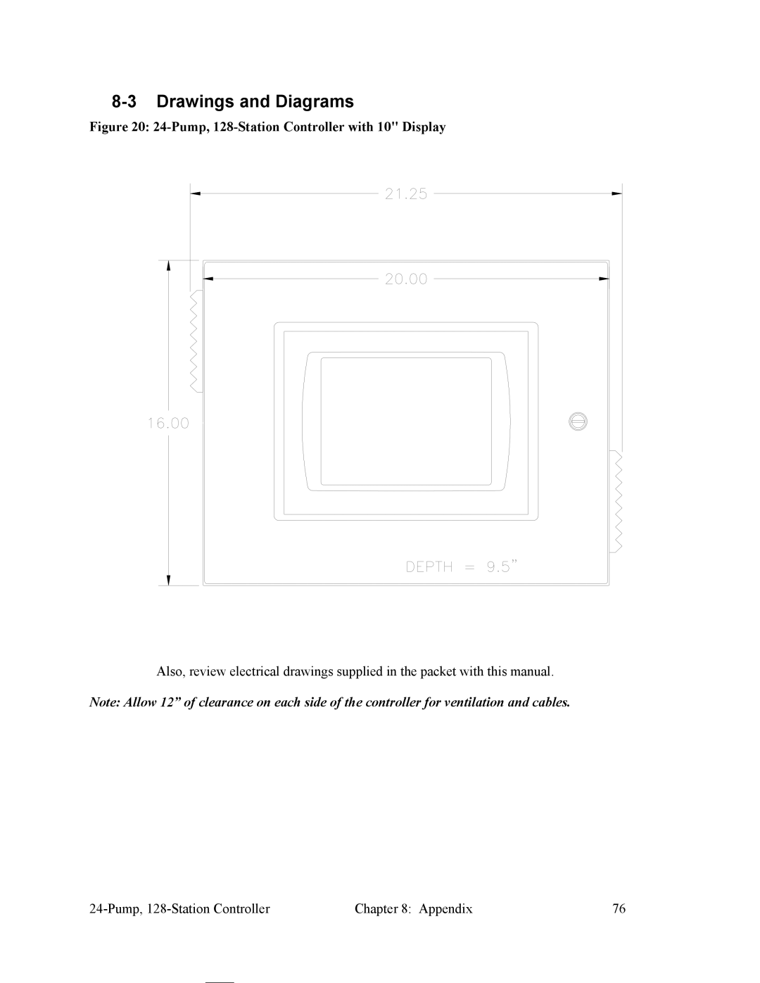
Figure 20: 24-Pump, 128-Station Controller with 10" Display
Also, review electrical drawings supplied in the packet with this manual.
Note: Allow 12” of clearance on each side of the controller for ventilation and cables.
Chapter 8: Appendix | 76 |
