Manuals
/
Sterling
/
Baby
/
Musical Table
Sterling
882.00255.00 CV3-655
specifications
Proper Vacuum Receiver Connections
Models:
882.00255.00 CV3-655
1
1
2
3
4
5
6
7
8
9
10
11
12
13
14
15
16
17
18
19
20
21
22
23
24
25
26
27
28
29
30
31
32
33
34
35
36
37
38
39
40
41
42
43
44
45
46
47
48
49
50
51
52
53
54
55
56
57
58
59
60
61
62
63
64
65
66
67
68
69
70
71
72
73
74
75
76
77
78
79
80
81
81
Download
81 pages
27.86 Kb
23
24
25
26
27
28
29
30
31
32
Troubleshooting
Install
Parts list
Error codes
Drawings and Diagrams
Setting Up Alarm Silences
Password
Connecting Vacuum Pumps
Warranty
Maintenance
Page 28
Image 28
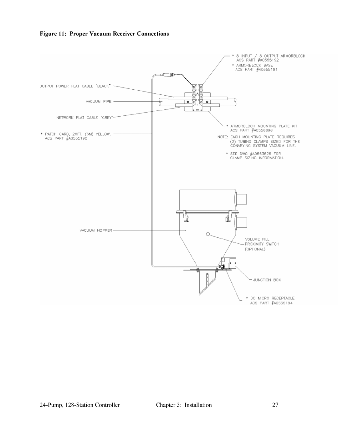
Figure 11: Proper Vacuum Receiver Connections
24-Pump,
128-Station
Controller
Chapter 3: Installation
27
Page 27
Page 29
Page 28
Image 28
Page 27
Page 29
Contents
SCC 24-Pump 128-Station Controller
Parts and Service Department
Shipping Information
Table of Contents
Maintenance
How to Use This Manual
Safety
Safety Symbols Used in this Manual
Wear Safety Glasses and Work Gloves
General Responsibility
Responsibility
Operator Responsibility
Maintenance Responsibility
Reporting a Safety Defect
Standard Features
Mechanical Features
Functional Description
Models Covered in This Manual
Optional Features
Safety Devices and Interlocks
Electrical Features
Controller Features
Safety Device Lock-Outs
Safety Circuit Standards
Fail Safe Operation
Installation
System Installation Overview
Uncrating
Mounting the Control Panel
Making Control Panel Power Drop Wiring Connections
Installing KwikLink Cable
Electrical Connections
Running KwikLink Cables
Setting Up and Installing Mounting Plates
Setting Up Mounting Plates
Installing Assembled Mounting Plates
Terminating Cable Runs
Installing Inside KwikLink Connectors with Blank Caps
Discard the standard resistor cap to eliminate confusion
Addressing ArmorBlocks
Addressing and Installing ArmorBlocks
ArmorBlock Address Ranges
Setting ArmorBlock Addresses
Using seal block to pierce cable
Installing KwikLink Connectors
Connecting the Controller to the Network
Connecting the Remote Interface to the Main Controller
Page
Connecting the Power Supply Enclosure to the Network
Proper Controller and Remote Interface Connections
Page
Proper Power Supply Enclosure Connections
Connecting Vacuum Receivers to the Network
24/128 8-Connector ArmorBlock Connections
Proper Vacuum Receiver Connections
Connecting Vacuum Pumps and Filter Chambers to the Network
Connecting Vacuum Pumps
Proper Vacuum Pump Connections, Standard XPD/XPC Pumps
Proper Vacuum Pump Connections, Xpdb Pump
Connecting Filter Chambers
Proper Filter Chamber Connections, Blowback
Proper Filter Chamber Connections, Implosion Type
Connecting Central Alarms to the Network
Proper Central Alarm Connections
Setup
Connector ArmorBlock Connections for Central Alarms
Setting Up the System
Setting the Number of Stations and the Number of Pumps
Checking Addressing and Wiring for System Components
Setting the Date/Time
Naming Purge Valves and Materials
Setting Up Alarm Silences
Alarm Horn Silence
Setting Up Pump Staging
Setting Up Stations
Setting Up a Single Station
Naming Stations
Copying Settings from One Station to Others
To copy the selected station’s settings to one other station
Setting Up Pumps
Setting Up a Single Pump
Page
Copying Settings from One Pump to Others
Naming Pumps
To copy the selected pump’s settings to one other pump
To copy the current pump’s settings to all other pumps
Finishing Setup Setting Up Passwords
Password Duration
Save/Restore Settings
Initial Startup
Overview
Operation
Starting and Stopping the System
Basic Tasks
Reviewing Station Status
Reviewing Pump Status
Color Label Description
Logging On and Logging Off
Enter the alphanumeric password
Enabling and Disabling Stations and Pumps
Reaching and Reading the Station Operator Screens
Reviewing and Adjusting Basic Station Settings
Navigating among the Station Operator Screens
Adjusting Convey Time and Dump Delay
Activating and Stopping Priority Convey for a Station
Changing the Mixture for a Remote Proportioning Valve
Advanced Tasks
Reviewing and Resetting a Pump Hour Meter
Transferring Stations to a Standby Pump
Page
Page
Reviewing Alarms
Alarms
Silencing Alarms
Maintenance
Preventative Maintenance
Corrective Maintenance
Network Scanner Module Considerations
Options for Station Setup
Configurable Settings
Memory Module Considerations
Name Description Options Default Conveying Options
Option Input
Pump, 128-Station Controller Configurable Settings
Pump, 128-Station Controller Configurable Settings
Options for Pump Setup
Pump, 128-Station Controller Configurable Settings
Troubleshooting
General Troubleshooting
Station Alarms
Alarm message Possible cause
Pump, 128-Station Controller Troubleshooting
Pump Alarms
System Alarms
Appendix
Warranty
Optional Components
Drawings and Diagrams
24-Pump, 128-Station Controller with 10 Display
Spare Parts List
Typical System Installation Layout
Returned Material Policy
Warranty Returns
Credit Returns
Controller Safety Tags
Safety Tag Information
Controller Identification Serial Number Tag
Service Department
Technical Assistance Contact Information
Parts Department
Sales Department
Top
Page
Image
Contents