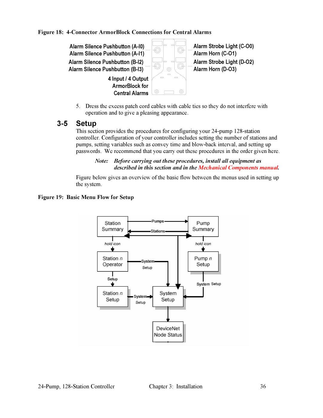
Figure 18: 4-Connector ArmorBlock Connections for Central Alarms
Alarm Silence Pushbutton | Alarm Strobe Light |
Alarm Silence Pushbutton | Alarm Horn |
Alarm Silence Pushbutton | Alarm Strobe Light |
Alarm Silence Pushbutton | Alarm Horn |
4 Input / 4 Output |
|
ArmorBlock for |
|
Central Alarms |
|
5.Dress the excess patch cord cables with cable ties so they do not interfere with operation and to give a pleasing appearance.
3-5 Setup
This section provides the procedures for configuring your
Note: Before carrying out these procedures, install all equipment as described in this section and in the Mechanical Components manual.
Figure below gives an overview of the basic flow between the menus used in setting up the system.
Figure 19: Basic Menu Flow for Setup
Chapter 3: Installation | 36 |