SDLT 600 Product Manual | Chapter 4: Installing Your Tape Drive |
|
|
|
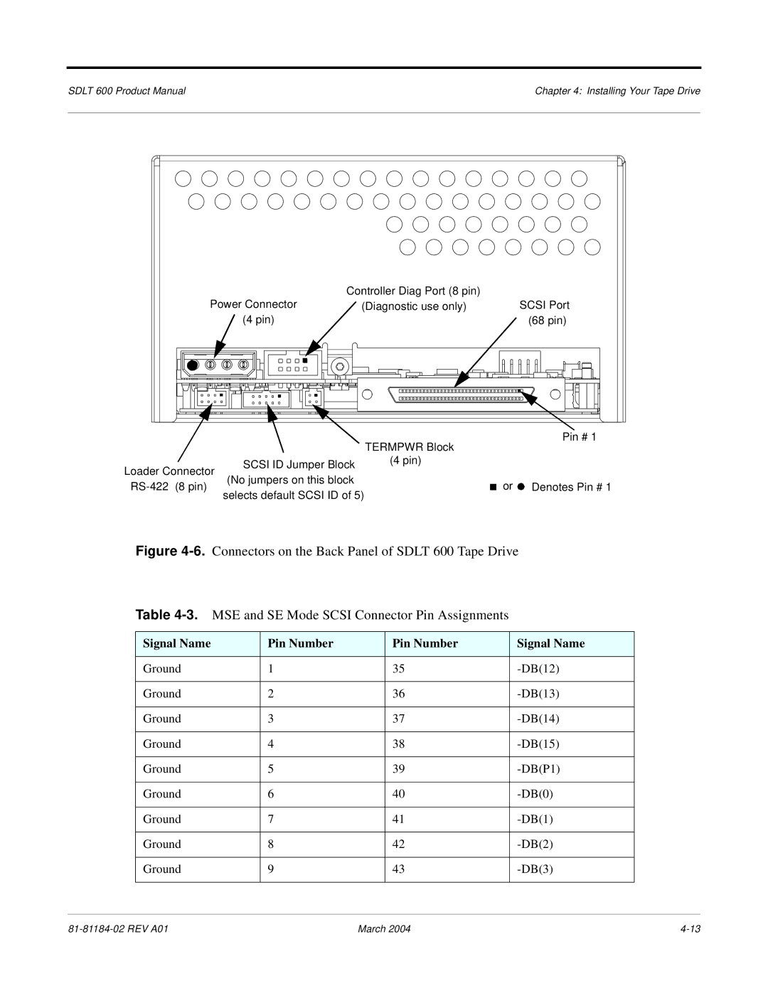
| Controller Diag Port (8 pin) |
Power Connector |
| (Diagnostic use only) |
(4 pin) |
|
|
|
|
|
|
|
|
|
| TERMPWR Block |
|
Loader Connector | SCSI ID Jumper Block | (4 pin) |
|
|
| ||
(No jumpers on this block |
|
| |
|
| ||
selects default SCSI ID of 5) |
|
| |
|
| ||
|
|
|
SCSI Port (68 pin)
Pin # 1
or ![]() Denotes Pin # 1
Denotes Pin # 1
Figure 4-6. Connectors on the Back Panel of SDLT 600 Tape Drive
Table 4-3. MSE and SE Mode SCSI Connector Pin Assignments
Signal Name | Pin Number | Pin Number | Signal Name |
|
|
|
|
Ground | 1 | 35 |
|
|
|
|
|
Ground | 2 | 36 |
|
|
|
|
|
Ground | 3 | 37 |
|
|
|
|
|
Ground | 4 | 38 |
|
|
|
|
|
Ground | 5 | 39 |
|
|
|
|
|
Ground | 6 | 40 |
|
|
|
|
|
Ground | 7 | 41 | |
|
|
|
|
Ground | 8 | 42 |
|
|
|
|
|
Ground | 9 | 43 |
|
|
|
|
|
March 2004 |