CHAPTER 5
5.2.7 Fan Removal
Two
Step 1. Remove the Rear Case Member (see Section 5.2.2).
Step 2. Disconnect the Fan Connector from the CPU Board.
Step 3. Remove the two
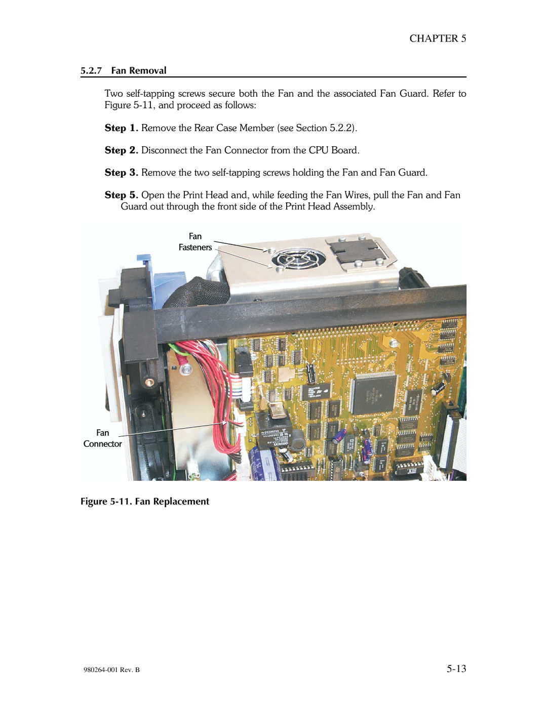
Step 5. Open the Print Head and, while feeding the Fan Wires, pull the Fan and Fan Guard out through the front side of the Print Head Assembly.