CHAPTER 5
5.2.12 Daughter Board Removal
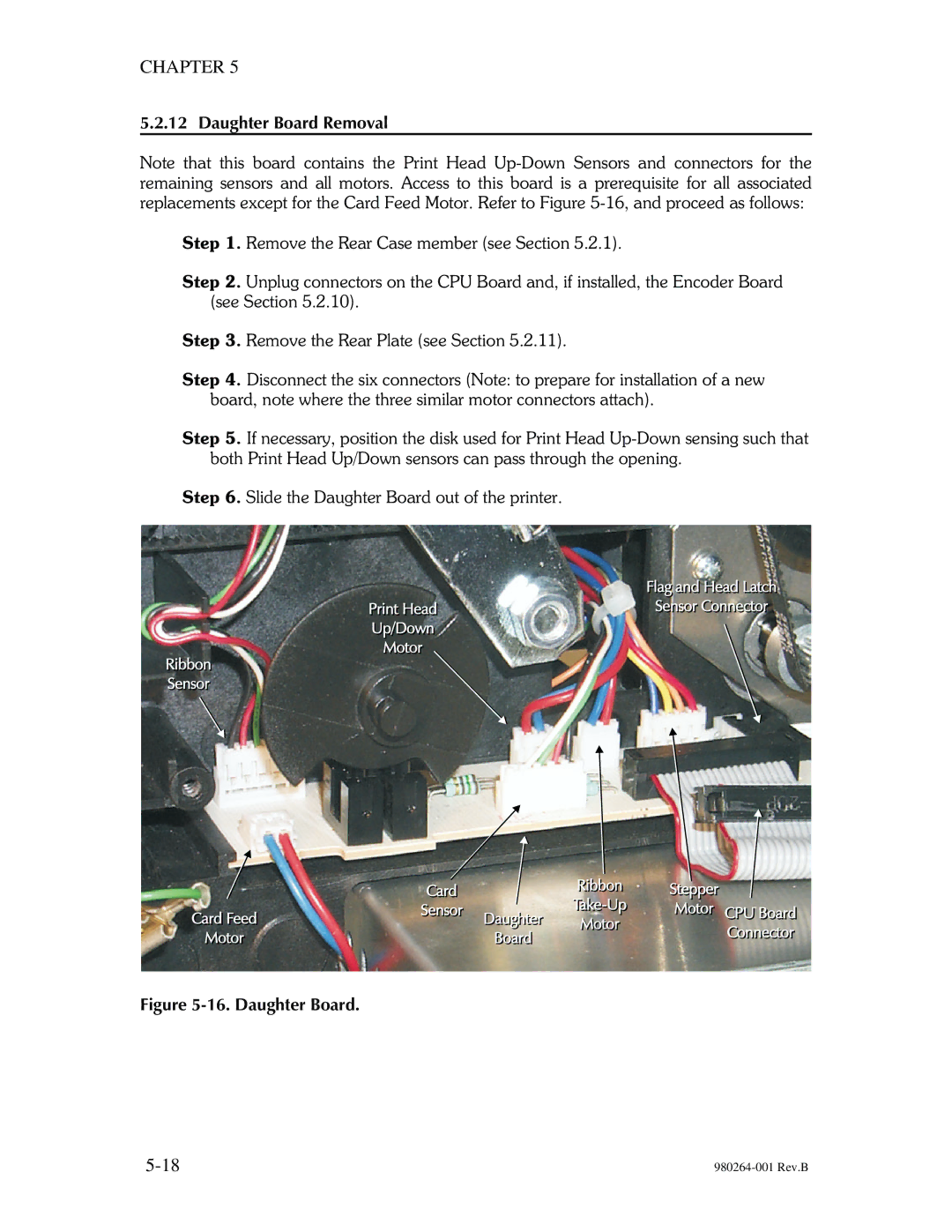
Note that this board contains the Print Head
Step 1. Remove the Rear Case member (see Section 5.2.1).
Step 2. Unplug connectors on the CPU Board and, if installed, the Encoder Board (see Section 5.2.10).
Step 3. Remove the Rear Plate (see Section 5.2.11).
Step 4. Disconnect the six connectors (Note: to prepare for installation of a new board, note where the three similar motor connectors attach).
Step 5. If necessary, position the disk used for Print Head
Step 6. Slide the Daughter Board out of the printer.
