CHAPTER 5
5.2.14 Rear Belt and O-Ring Removal
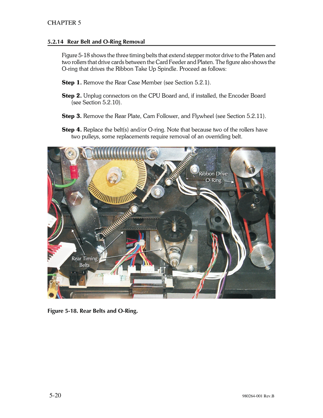
Figure 5-18 shows the three timing belts that extend stepper motor drive to the Platen and two rollers that drive cards between the Card Feeder and Platen. The figure also shows the O-ring that drives the Ribbon Take Up Spindle. Proceed as follows:
Step 1. Remove the Rear Case Member (see Section 5.2.1).
Step 2. Unplug connectors on the CPU Board and, if installed, the Encoder Board (see Section 5.2.10).
Step 3. Remove the Rear Plate, Cam Follower, and Flywheel (see Section 5.2.11).
Step 4. Replace the belt(s) and/or
