4 Replacement Procedures | 4.32 Modem jack/FM |
4.32 Modem jack/FM jack/DC-IN jack/right LED
Removing the Modem jack/FM jack/DC-IN jack/right LED
The following describes the procedure for removing the Modem jack/FM
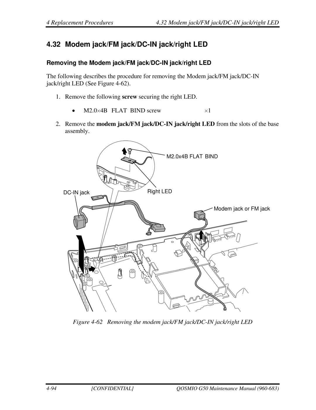
1. Remove the following screw securing the right LED.
• M2.0⋅4B FLAT BIND screw | ⋅1 |
2.Remove the modem jack/FM
M2.0x4B FLAT BIND
Right LED |
![]() Modem jack or FM jack
Modem jack or FM jack
Figure 4-62 Removing the modem jack/FM jack/DC-IN jack/right LED
[CONFIDENTIAL] | QOSMIO G50 Maintenance Manual |