5.6 Interrupt Input Function
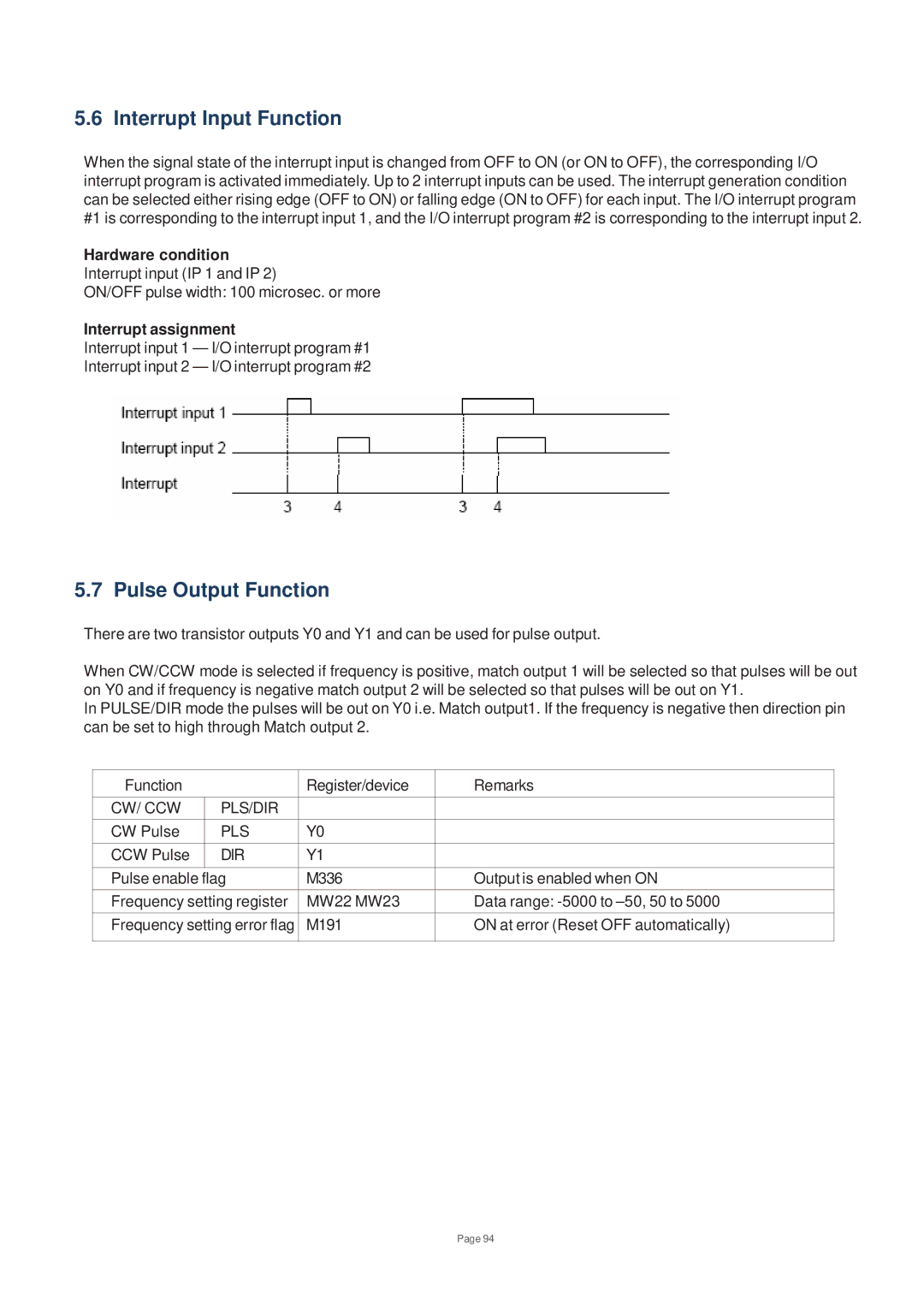
When the signal state of the interrupt input is changed from OFF to ON (or ON to OFF), the corresponding I/O interrupt program is activated immediately. Up to 2 interrupt inputs can be used. The interrupt generation condition can be selected either rising edge (OFF to ON) or falling edge (ON to OFF) for each input. The I/O interrupt program #1 is corresponding to the interrupt input 1, and the I/O interrupt program #2 is corresponding to the interrupt input 2.
Hardware condition
Interrupt input (IP 1 and IP 2)
ON/OFF pulse width: 100 microsec. or more
Interrupt assignment
Interrupt input 1 — I/O interrupt program #1
Interrupt input 2 — I/O interrupt program #2
5.7 Pulse Output Function
There are two transistor outputs Y0 and Y1 and can be used for pulse output.
When CW/CCW mode is selected if frequency is positive, match output 1 will be selected so that pulses will be out on Y0 and if frequency is negative match output 2 will be selected so that pulses will be out on Y1.
In PULSE/DIR mode the pulses will be out on Y0 i.e. Match output1. If the frequency is negative then direction pin can be set to high through Match output 2.
Function |
| Register/device | Remarks |
CW/ CCW | PLS/DIR |
|
|
CW Pulse | PLS | Y0 |
|
CCW Pulse | DIR | Y1 |
|
|
|
|
|
Pulse enable flag | M336 | Output is enabled when ON | |
Frequency setting register | MW22 MW23 | Data range: | |
Frequency setting error flag | M191 | ON at error (Reset OFF automatically) | |
|
|
|
|
Page 94