Manuals
/
Toshiba
/
Video Game
/
Console
Toshiba
V200
user manual
L1 to L6 are A.C. Load
Models:
V200
1
39
140
140
Download
140 pages
15.85 Kb
36
37
38
39
40
41
42
43
Troubleshooting
Specification
Install
Wiring Diagram for GDO216P**S
Error Mode
Timer Interrupt Program
Wire RTD
Maintenance
Configuration
Environmental Problem
Page 39
Image 39
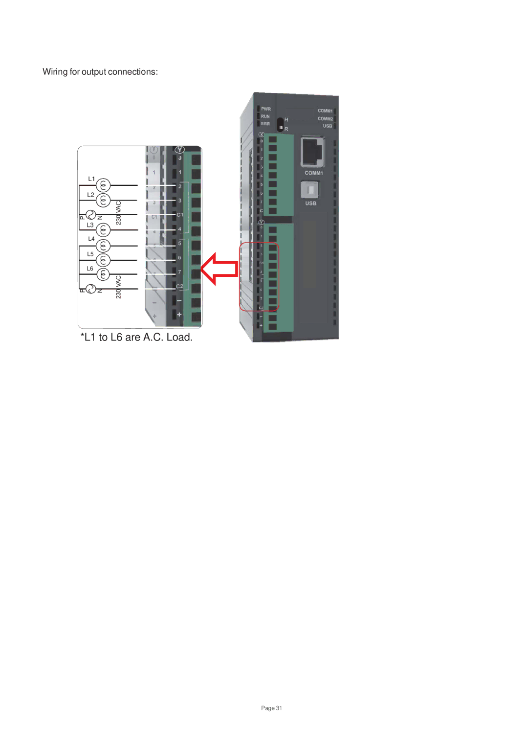
Wiring for output connections:
L1
L2
P
N
L3
L4
L5
L6
P
N
230 VAC
VAC
*L1 to L6 are A.C. Load.
Page 31
Page 38
Page 40
Page 39
Image 39
Page 38
Page 40
Contents
USER’S Manual Setup & Operation
Manual’s Purpose and Scope
Important Notice
Manual Revisions
Table of Contents
Input XW, Output YW and Configuration MW Register Allocation
106
127
General Safety Instructions & Information
Page
Electrical Hazard
Equipment Warning Labels
Qualified Personnel shall
Preparation
Installation Precautions
He M etal Of C o n d u it Is N o t An Accep tab le Gro u n d
Connection, Protection & Setup
Page
System Integration Precautions
CE Marking
3rd Party Safety Certifications
Introduction
1 V200 Basics
Purpose of this Manual
RAM 1GB
Programming Computer
Device Recommended
RAM
V200 Features
V200 Overview
What is a V200 Series Controller
Scada PLC OIS
OIS
How V200 Works
Start
Page
Error Mode
Page
Error Mode
Hold Mode
Page
Page
GDD288P*S
V200 Series Specifications
GDO216P*S
GDO216N*S
Comparison between basic models GPU288*3S & GPU232*3S
Comparison between basic models GPU200*3S & GPU236*3S
GPU288*3S
Specification for Basic Models
Type O/P
L1 to L6 are A.C. Load
GPU232*3S
GPU200*3S
GPU236 -Under Development
GDI216**S
Specification for Expansion Models
GDO216P*S PNP Type transistor output
Wiring Diagram for GDO216P**S
GDO216N*3S NPN Type transistor output
Wiring Diagram for GDO216N**S
GDR216**S Relay Type output
L1 to L16 are A.C. Load
FTB
L1 to L8 are A.C. Load
Wiring diagram for output connections
Wiring diagram for output connections
GAD208**S
Current mode connections
RTD PT100
GRT208**S
Wiring Diagram of input connection for GRT208**S
GDA204**S
Iout
Analog Inputs Analog Outputs
GAA242**S
Improper Connection for current
Wire RTD
1000 Ω
Hardware
Environmental Consideration
Unpacking The Unit
Managing Electrostatic Discharge
CE Compliance
Safety Precautions
Page
Installation Instructions
V200 PLC with DIN rail slider Front View Rear View
Page
FIG-4
Communication Ports
Wiring Diagram
COM2 Port Details
PC Side V200 Side
Communication Cables
Before YOU Begin
Welcome to OIL-DS Setup Wizard
Installing OIL-DS Configuration Software
Installing OIL-DS
OIL-DS has been successfully installed Click Close to exit
Steps for starting OIL-DS Software
Uninstalling OIL-DS Software
Launching Ladder Editor in OIL-DS
Page
Creating Sample Ladder
Page
Following screen will appears if compilation is successful
Configuration
Configuring V200 using OIL-DS
Page
Page
Tag Database
COM3
COM1
Page
Always OFF
Always on
Input XW, Output YW and Configuration MW Register Allocation
Page
Channel Type Selection Values Table
Special Input and Output Options
Special I/O Function Overview
High Speed Counter Design
A 9 8 7 6 5 4 3 2 1 0
CW/CCW
D C
Function Register/device Remarks Channel
Single Phase Speed Counter
Single Phase Speed Counter
Edge count
Quadrature Bi-pulse Counter
Function Register/device Remarks
PLS
Interrupt Input Function
Pulse Output Function
CW/ CCW PLS/DIR
PWM Output Function
Operating Systems Overview
Operating System Overview
Mode Selection
Programming Information
Devices Registers
Double click on each Slot to assign model name
GDD288N
Page
Page
M0513
Coils
GDD216P
Memory Allocation of XW, YW and MW
GDO216P
GDO216N
Page
Index Modification
Page
LSI
Real-time Clock / Calendar
Main Program
User Program
Timer Interrupt Program
Sub-Program #
4 I/O Interrupt Program
Subroutines
Rung number
Programming Language
Program Execution Sequence
Troubleshooting
RUN LED
Troubleshooting Procedure
Power Supply Check
CPU Check
Program Check
Input Check
Output Check
Environmental Problem
Self Diagnostics
CPU error
Event Info1 Special Meaning Check at Device Countermeasures
ROM Errors
Register / Coil Tag Name Read / Write Description
Maintenance and Checks
Precautions During Operation
Daily Checks
PWR
RUN
Periodic Checks
Spare Parts
Toshiba Industrial Products
Top
Page
Image
Contents