GAA242**S
Analog Inputs
Analog Outputs
Isolation
Connection method Resolution Accuracy Nonlinearity
Input Impedance
4 Universal Input Channels Voltage Input 0 - 10 V Current Input
mV
2 Output channels
Voltage 0 - 10 V (Min Load 1000 ohm) or
Current 4 - 20 mA (Max load 500 ohm)
Isolation between analog and digital section. No
Removable terminals (3.81mm pitch) 16 Bit
0.2% of Full Scale 0.04% Max.
1Mohm (Voltage/mV/TC/RTD mode) typically 30 ohm (Current mode)
Power Rating (Back Plane)
Digital Side: Power derived from expansion slot
Voltage Rating | 3.75 VDC derived from |
| base model |
|
|
Current Rating | Upto 80mA |
|
|
|
|
Power Supply: | 24VDC, 150mA |
|
|
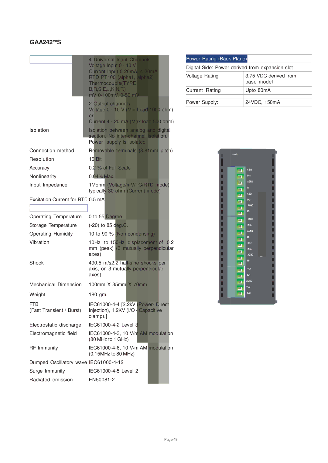
PWR
CS11
IN1+
AGND
I1-
CS21
Excitation Current for RTD 0.5 mA
General
Operating Temperature | 0 to 55 Degree. |
Storage Temperature | |
Operating Humidity | 10 to 90 % (Non condensing) |
Vibration | 10Hz to 150Hz ,displacement of 0.2 |
| mm (peak) (3 mutually perpendicular |
| axes) |
Shock | 490.5 m/s2,2 |
| axis, on 3 mutually perpendicular |
| axes) |
Mechanical Dimension | 100mm X 35mm X 70mm |
Weight | 180 gm. |
FTB | |
(Fast Transient / Burst) | Injection), 1.2KV (I/O - Capacitive |
| clamp).] |
Electrostatic discharge | |
Electromagnetic field | |
| (80 MHz to 1 GHz) |
RF Immunity | |
| (0.15MHz to 80 MHz) |
Dumped Oscillatory wave | |
Surge Immunity | |
Radiated emission | |
IN2+
AGND
I2-
CS31 |
IN3+ |
AGND |
I3- |
CS41 |
IN4+ |
AGND |
I4- |
VO1
IO1
AGND
VO2
IO2
Page 49