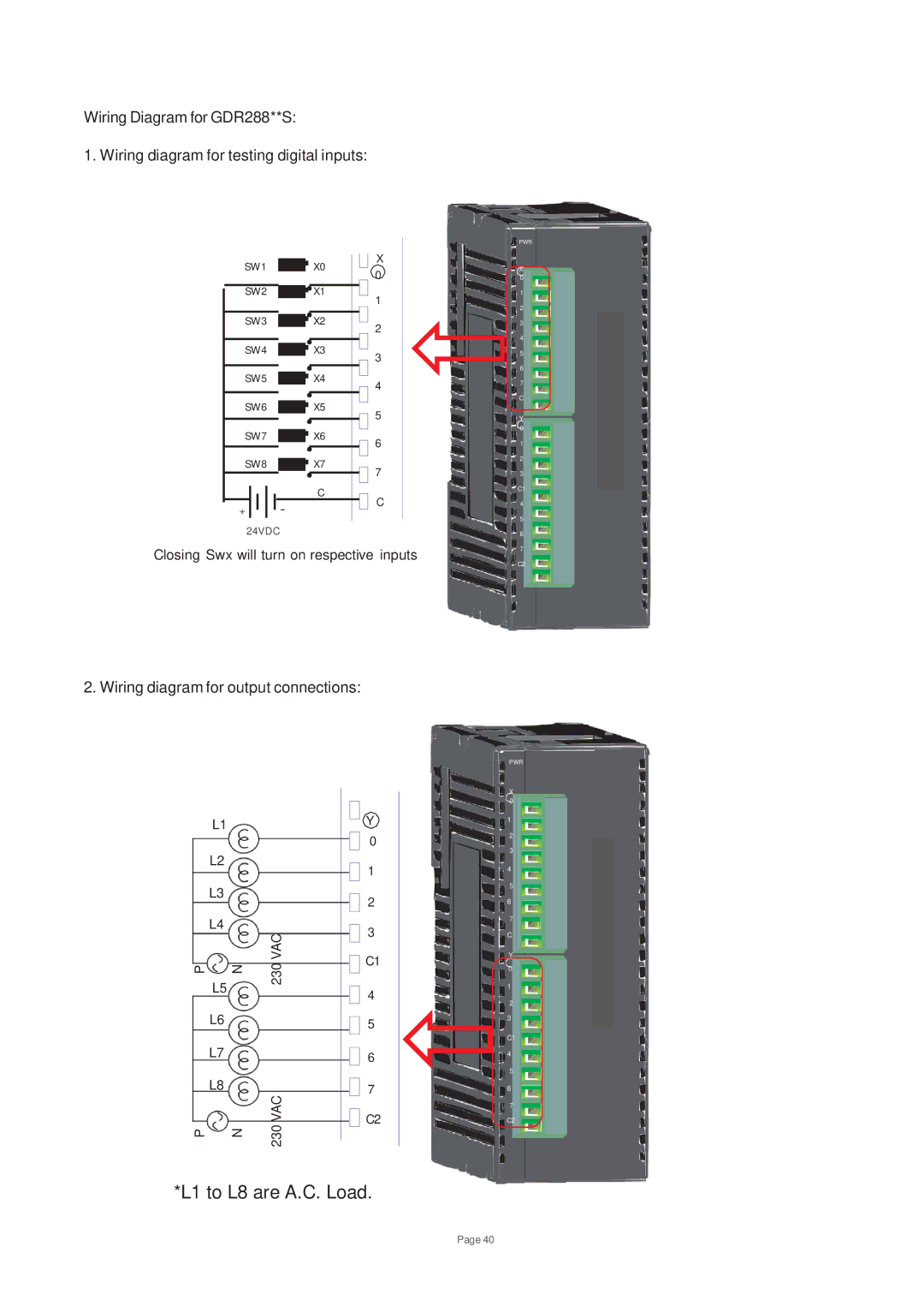
Wiring Diagram for GDR288**S:
1. Wiring diagram for testing digital inputs:
SW1 |
| X0 | X |
| 0 | ||
|
|
| |
SW2 |
| X1 | 1 |
|
|
| |
SW3 |
| X2 | 2 |
|
|
| |
SW4 |
| X3 | 3 |
|
|
| |
SW5 |
| X4 | 4 |
|
|
| |
SW6 |
| X5 | 5 |
|
|
| |
SW7 |
| X6 | 6 |
|
|
| |
SW8 |
| X7 | 7 |
|
|
| |
| - | C | C |
+ |
| ||
|
| ||
24VDC |
|
|
|
Closing Swx will turn on respective inputs
PWR
X 0
1
2
3
4
5
6
7 C
Y |
0 |
1 |
2 |
3 |
C1 |
4 |
5 |
6 |
7 |
C2 |
2. Wiring diagram for output connections:
| L1 |
| Y | |
|
|
| 0 | |
| L2 |
| 1 | |
|
|
| ||
| L3 |
| 2 | |
|
|
| ||
| L4 | VAC | 3 | |
|
| |||
|
| C1 | ||
P | N | 230 | ||
| ||||
| L5 |
| 4 | |
|
|
| ||
| L6 |
| 5 | |
| L7 |
| 6 | |
| L8 | VAC | 7 | |
|
| C2 | ||
P | N | 230 | ||
| ||||
|
|
|
*L1 to L8 are A.C. Load.
PWR
X 0
1
2
3
4
5
6
7 C
Y 0
1
2
3
C1
4
5
6
7
C2
Page 40