5.1 Special I/O Function Overview
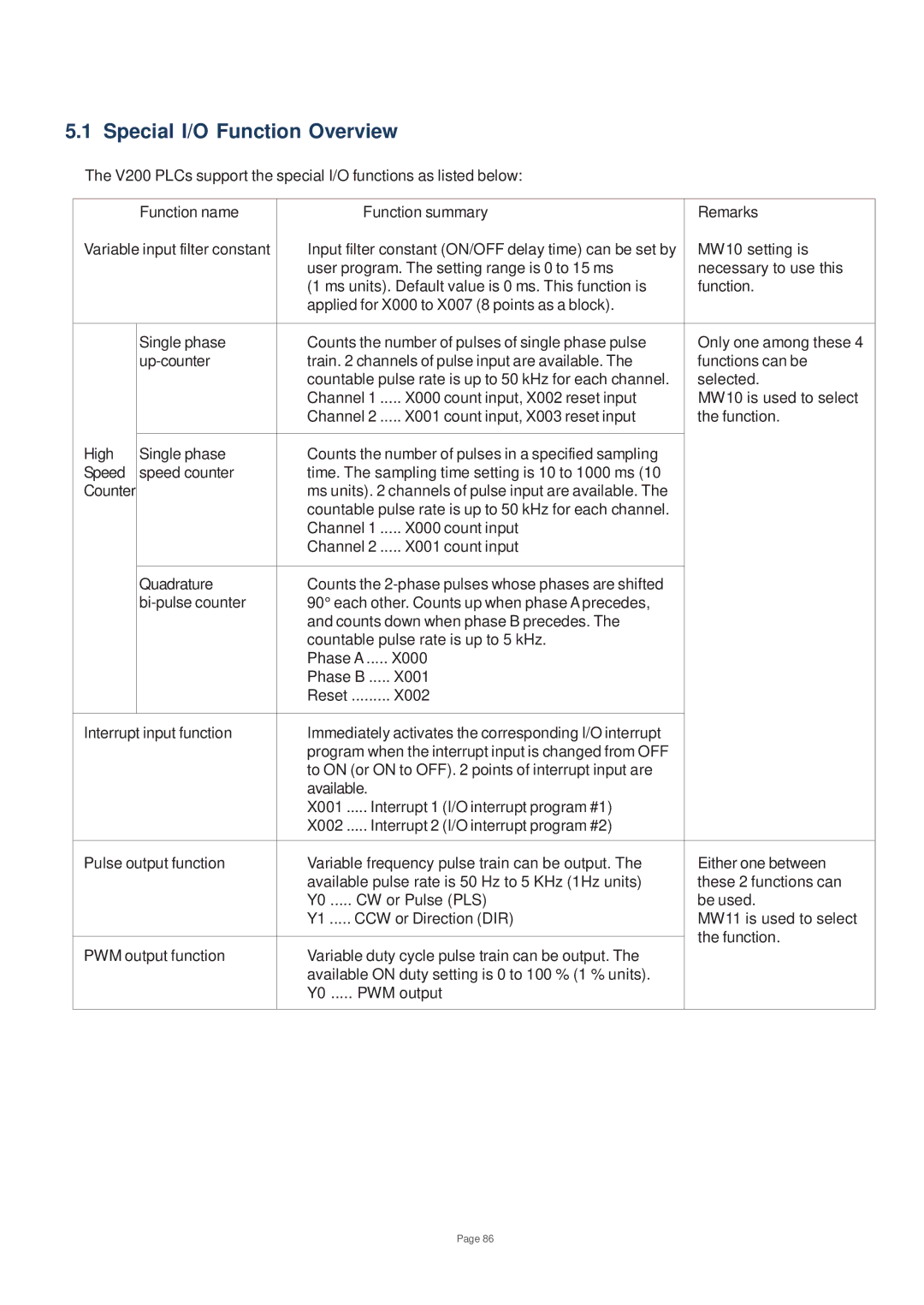
The V200 PLCs support the special I/O functions as listed below:
| Function name | Function summary | Remarks | |
Variable input filter constant | Input filter constant (ON/OFF delay time) can be set by | MW10 setting is | ||
|
| user program. The setting range is 0 to 15 ms | necessary to use this | |
|
| (1 ms units). Default value is 0 ms. This function is | function. | |
|
| applied for X000 to X007 (8 points as a block). |
| |
|
|
|
| |
| Single phase | Counts the number of pulses of single phase pulse | Only one among these 4 | |
| train. 2 channels of pulse input are available. The | functions can be | ||
|
| countable pulse rate is up to 50 kHz for each channel. | selected. | |
|
| Channel 1 ..... X000 count input, X002 reset input | MW10 is used to select | |
|
| Channel 2 ..... X001 count input, X003 reset input | the function. | |
|
|
|
| |
High | Single phase | Counts the number of pulses in a specified sampling |
| |
Speed | speed counter | time. The sampling time setting is 10 to 1000 ms (10 |
| |
Counter |
| ms units). 2 channels of pulse input are available. The |
| |
|
| countable pulse rate is up to 50 kHz for each channel. |
| |
|
| Channel 1 ..... X000 count input |
| |
|
| Channel 2 ..... X001 count input |
| |
|
|
|
| |
| Quadrature | Counts the |
| |
| 90° each other. Counts up when phase A precedes, |
| ||
|
| and counts down when phase B precedes. The |
| |
|
| countable pulse rate is up to 5 kHz. |
| |
|
| Phase A ..... X000 |
| |
|
| Phase B ..... X001 |
| |
|
| Reset ......... X002 |
| |
|
|
|
| |
Interrupt input function | Immediately activates the corresponding I/O interrupt |
| ||
|
| program when the interrupt input is changed from OFF |
| |
|
| to ON (or ON to OFF). 2 points of interrupt input are |
| |
|
| available. |
| |
|
| X001 ..... Interrupt 1 (I/O interrupt program #1) |
| |
|
| X002 ..... Interrupt 2 (I/O interrupt program #2) |
| |
|
|
| ||
Pulse output function | Variable frequency pulse train can be output. The | Either one between | ||
|
| available pulse rate is 50 Hz to 5 KHz (1Hz units) | these 2 functions can | |
|
| Y0 ..... CW or Pulse (PLS) | be used. | |
|
| Y1 ..... CCW or Direction (DIR) | MW11 is used to select | |
|
|
| the function. | |
PWM output function | Variable duty cycle pulse train can be output. The | |||
| ||||
|
| available ON duty setting is 0 to 100 % (1 % units). |
| |
|
| Y0 ..... PWM output |
| |
|
|
|
| |
Page 86