5.4 Single Phase Speed Counter
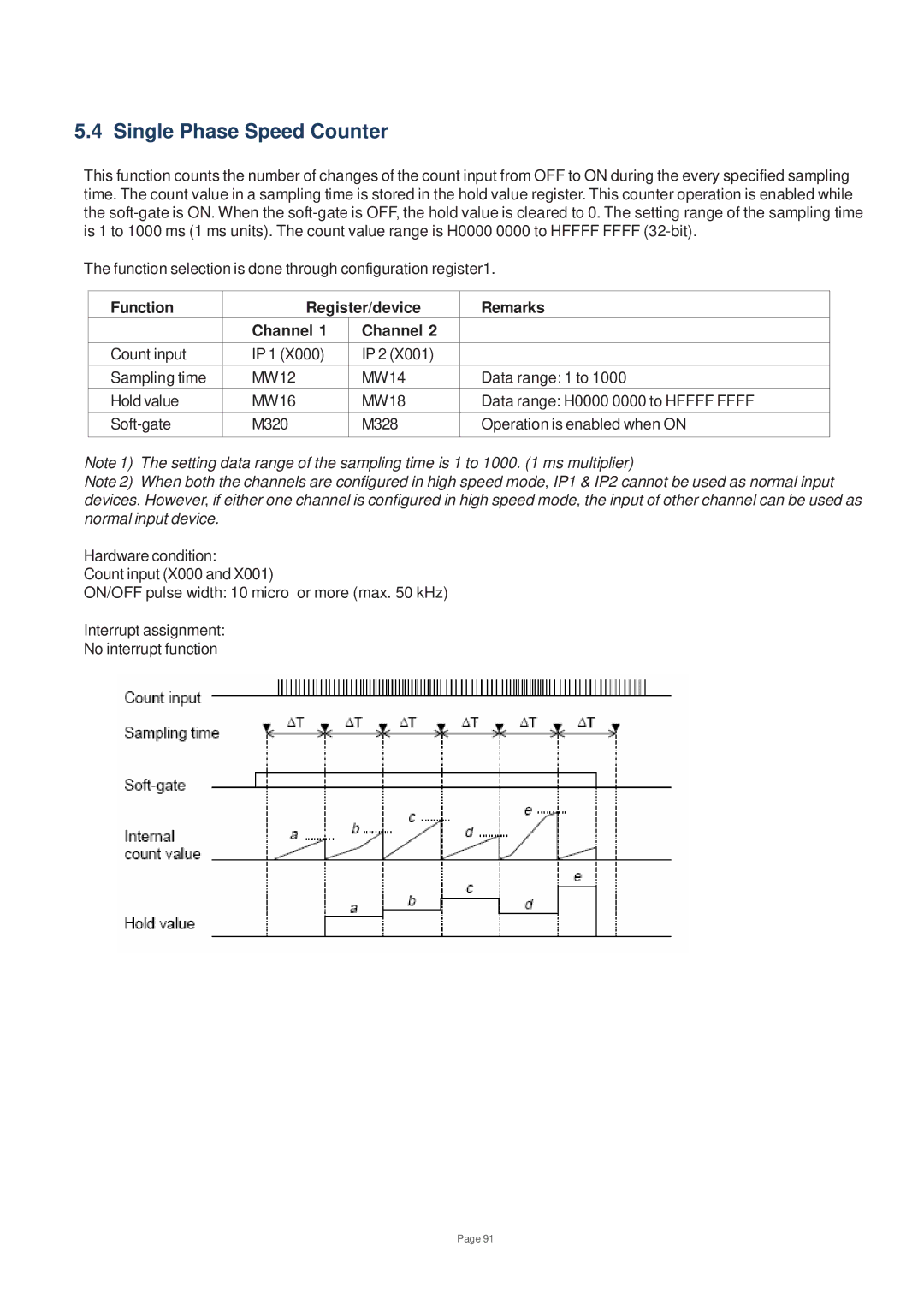
This function counts the number of changes of the count input from OFF to ON during the every specified sampling time. The count value in a sampling time is stored in the hold value register. This counter operation is enabled while the
The function selection is done through configuration register1.
Function | Register/device | Remarks | |
| Channel 1 | Channel 2 |
|
Count input | IP 1 (X000) | IP 2 (X001) |
|
Sampling time | MW12 | MW14 | Data range: 1 to 1000 |
Hold value | MW16 | MW18 | Data range: H0000 0000 to HFFFF FFFF |
M320 | M328 | Operation is enabled when ON | |
|
|
|
|
Note 1) The setting data range of the sampling time is 1 to 1000. (1 ms multiplier)
Note 2) When both the channels are configured in high speed mode, IP1 & IP2 cannot be used as normal input devices. However, if either one channel is configured in high speed mode, the input of other channel can be used as normal input device.
Hardware condition:
Count input (X000 and X001)
ON/OFF pulse width: 10 micro or more (max. 50 kHz)
Interrupt assignment:
No interrupt function
Page 91