4.3 Input (XW), Output (YW) and Configuration (MW) Register Allocation
For Digital Expansion Models:
The Physical Inputs and Outputs in the Expansion modules are accessed using XW and YW registers respectively. The digital inputs in the Digital Expansion Models are updated in the (Input) XW registers.
The expansion model may have XW or YW registers depending on availability of the physical input/outputs for that model type. As given in Section 7.2 ‘Memory Allocation of XW, YW and MW’, different expansion models have different number of XW, YW and MW memory assigned for them in the base model.
e.g. The digital expansion model GDI216**S has 1 XW register memory assigned for it.
There are no outputs so no YW memory. So the input condition of GDI2816**S is read in Input Register XWxx00. Same inputs are shown in the input coils Xxx000 to Xxx015. Here xx denotes the slot number in which the expansion model is connected to V200.
Similarly, outputs register for GRO216**S model is YWxx00. For GDR288**S model it has one XW and one YW, but only 8 bits are used. Other bits are not used.
For Analog Expansion Models:
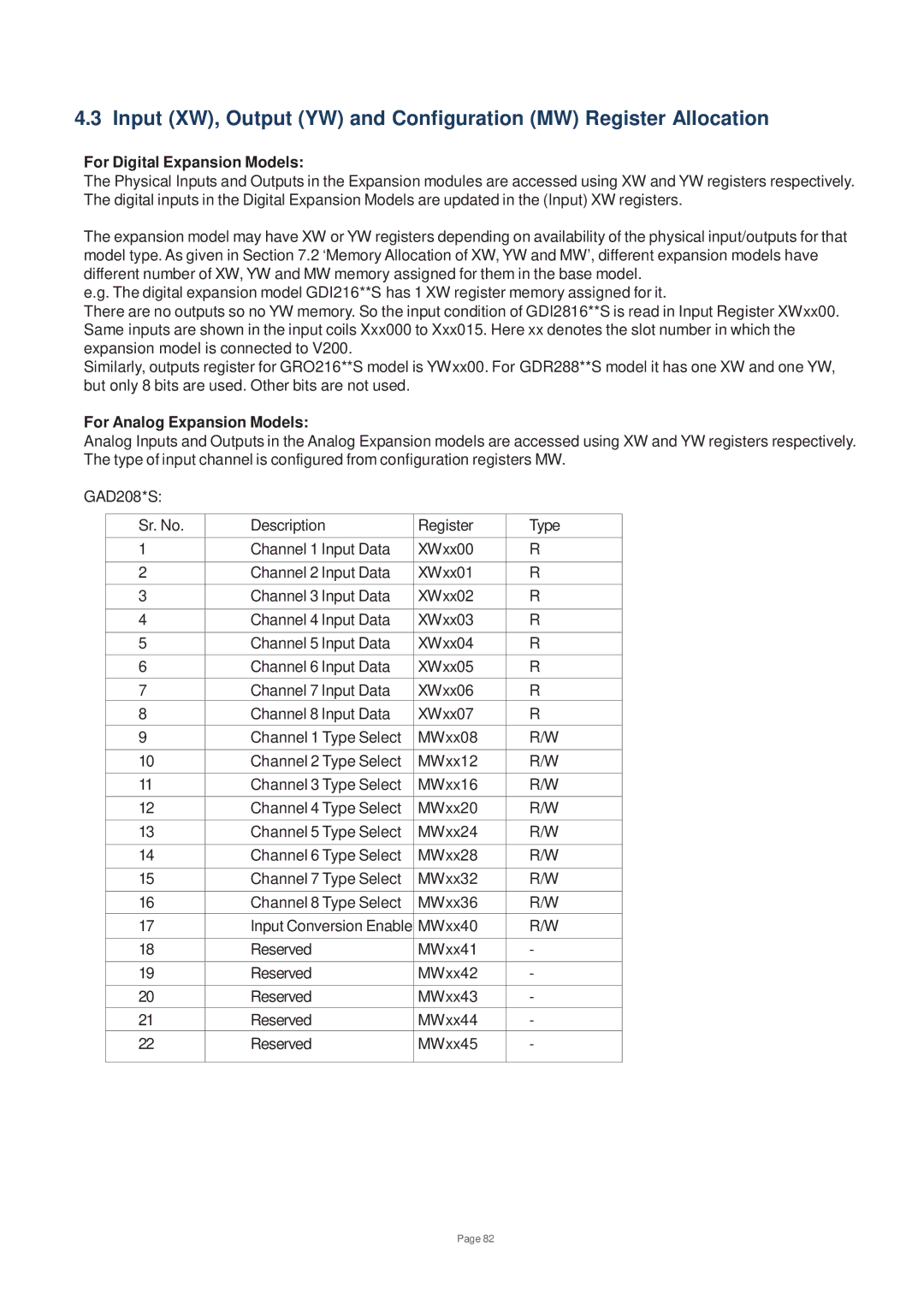
Analog Inputs and Outputs in the Analog Expansion models are accessed using XW and YW registers respectively. The type of input channel is configured from configuration registers MW.
GAD208*S:
Sr. No. | Description | Register | Type |
1 | Channel 1 Input Data | XWxx00 | R |
|
|
|
|
2 | Channel 2 Input Data | XWxx01 | R |
3 | Channel 3 Input Data | XWxx02 | R |
|
|
|
|
4 | Channel 4 Input Data | XWxx03 | R |
|
|
|
|
5 | Channel 5 Input Data | XWxx04 | R |
6 | Channel 6 Input Data | XWxx05 | R |
7 | Channel 7 Input Data | XWxx06 | R |
8 | Channel 8 Input Data | XWxx07 | R |
9 | Channel 1 Type Select | MWxx08 | R/W |
10 | Channel 2 Type Select | MWxx12 | R/W |
11 | Channel 3 Type Select | MWxx16 | R/W |
12 | Channel 4 Type Select | MWxx20 | R/W |
13 | Channel 5 Type Select | MWxx24 | R/W |
|
|
|
|
14 | Channel 6 Type Select | MWxx28 | R/W |
|
|
|
|
15 | Channel 7 Type Select | MWxx32 | R/W |
|
|
|
|
16 | Channel 8 Type Select | MWxx36 | R/W |
17 | Input Conversion Enable | MWxx40 | R/W |
|
|
|
|
18 | Reserved | MWxx41 | - |
|
|
|
|
19 | Reserved | MWxx42 | - |
|
|
|
|
20 | Reserved | MWxx43 | - |
21 | Reserved | MWxx44 | - |
22 | Reserved | MWxx45 | - |
|
|
|
|
Page 82