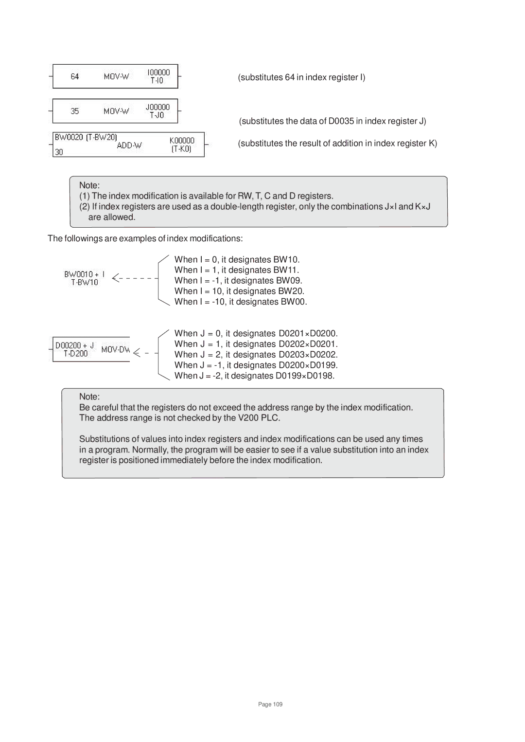
(substitutes 64 in index register I)
(substitutes the data of D0035 in index register J)
(substitutes the result of addition in index register K)
Note:
(1)The index modification is available for RW, T, C and D registers.
(2)If index registers are used as a
The followings are examples of index modifications:
When I = 0, it designates BW10.
When I = 1, it designates BW11.
When I =
When I = 10, it designates BW20.
When I =
When J = 0, it designates D0201×D0200.
When J = 1, it designates D0202×D0201.
When J = 2, it designates D0203×D0202.
When J =
When J =
Note:
Be careful that the registers do not exceed the address range by the index modification. The address range is not checked by the V200 PLC.
Substitutions of values into index registers and index modifications can be used any times in a program. Normally, the program will be easier to see if a value substitution into an index register is positioned immediately before the index modification.
Page 109