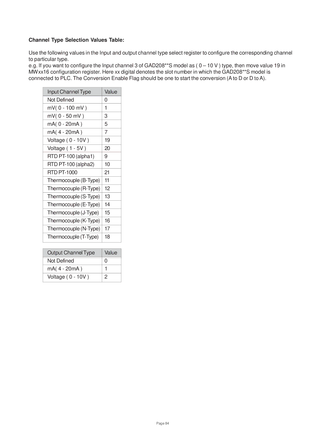
Channel Type Selection Values Table:
Use the following values in the Input and output channel type select register to configure the corresponding channel to particular type.
e.g. If you want to configure the Input channel 3 of GAD208**S model as ( 0 – 10 V ) type, then move value 19 in MWxx16 configuration register. Here xx digital denotes the slot number in which the GAD208**S model is connected to PLC. The Conversion Enable Flag should be one to start the conversion (A to D or D to A).
Input Channel Type |
| Value |
| ||
|
|
|
Not Defined |
| 0 |
mV( 0 - 100 mV ) | 1 | |
mV( 0 - 50 mV ) | 3 | |
mA( 0 - 20mA ) | 5 | |
|
| |
mA( 4 - 20mA ) | 7 | |
Voltage ( 0 - 10V ) | 19 | |
|
| |
Voltage ( 1 - 5V ) | 20 | |
RTD | 9 | |
|
| |
RTD | 10 | |
|
| |
RTD | 21 | |
Thermocouple | 11 | |
|
| |
Thermocouple | 12 | |
|
| |
Thermocouple | 13 | |
Thermocouple | 14 | |
Thermocouple | 15 | |
|
| |
Thermocouple | 16 | |
|
| |
Thermocouple | 17 | |
|
| |
Thermocouple | 18 | |
|
|
|
|
|
|
Output Channel Type |
| Value |
|
|
|
Not Defined | 0 | |
mA( 4 - 20mA ) | 1 | |
|
| |
Voltage ( 0 - 10V ) | 2 | |
|
|
|
Page 84