iPump 6420 User’s Manual
Rack Installation
The iPump 6420 is sized at 1 RU and should be mounted in an
1)First, install angle brackets or
NOTE: Use of rack supports with cutouts on the sides that allow air circulation are also permitted.(Wegener P/N
2)Place the iPump 6420 on its supports and use four anchor screws or bolts and nuts to secure the unit's front brackets to the rack.
3)Do not block any of the ventilation or fan opening on the front, side, or rear of the unit. Support arrangements that do not allow adequate air flow or that block the openings on front, side and rear vents may result in overheating and damage to the iPump 6420.
4)The front brackets must be secured to the rack. If front brackets are left unsecured, the unit may shift forward and fall from the rack during installation or operation. Failure to secure the front brackets may result in personal injury and/or damage to the equipment.
5)Locate the iPump 6420 and its cables to avoid impacts, spills, and pulling cables and to ensure sufficient air flow. Failure to locate the iPump 6420 in a proper environment may result in damage to the equipment.
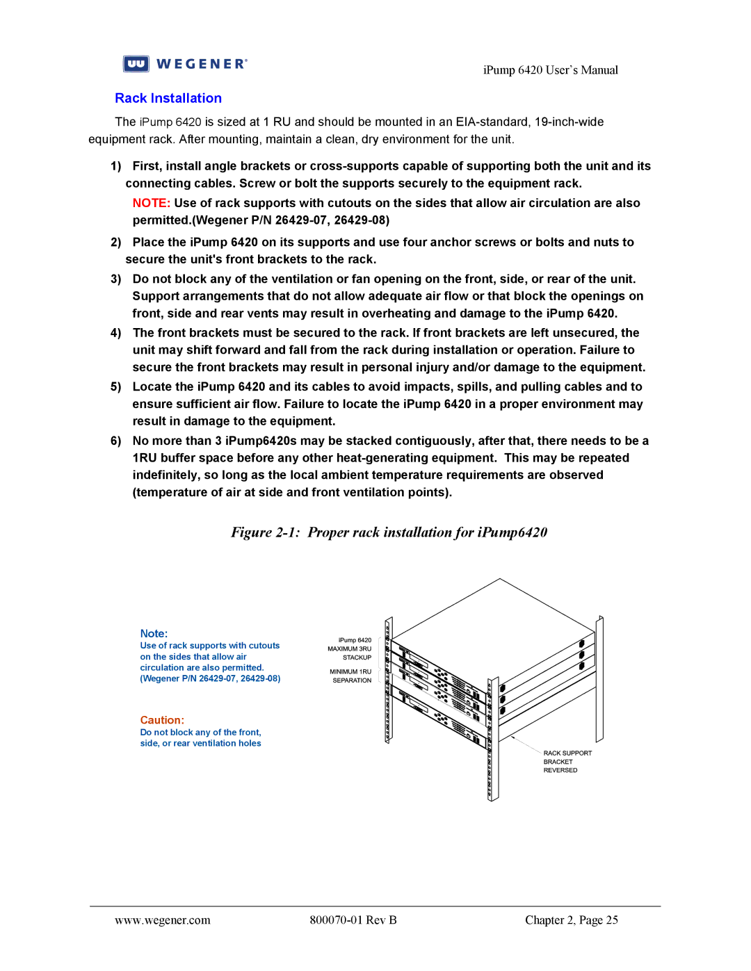
6)No more than 3 iPump6420s may be stacked contiguously, after that, there needs to be a 1RU buffer space before any other
Figure 2-1: Proper rack installation for iPump6420
Note:
Use of rack supports with cutouts on the sides that allow air circulation are also permitted. (Wegener P/N
Caution:
Do not block any of the front, side, or rear ventilation holes
www.wegener.com |
| Chapter 2, Page 25 |