IPump
Wegener Communications, Inc
Table of Contents
This page intentionally left blank
Store/Forward System overview
General Information
Wegener Communications, Inc
Manual Overview
Basic Store/Forward Mission
IPump 6420 Overview
IPump 6420 User’s Manual
Overview, Store/Forward Radio Networks featuring iPump6420
Using Playlists as indirection, for local inserts
Supplemental capabilities
Automation Mode
Premium Features
ShowShifting
Functional Description
TimeZone Delay
MP3 Codec
IPump 6420 User’s Manual
IPump 6420 User’s Manual
IPump6420 Functional Block Diagram
LNB DC Power
IPump 6420 Specifications
MPEG/DVB
Supplied for two main audios
Output only
Optional
FCC
Safety Summary
Term Definition
Glossary of Terms and Abbreviations
LCD
Rev B
Establishing Compel Network Control
Installation
Location and Mounting
Unpacking and Inspection
Proper rack installation for iPump6420
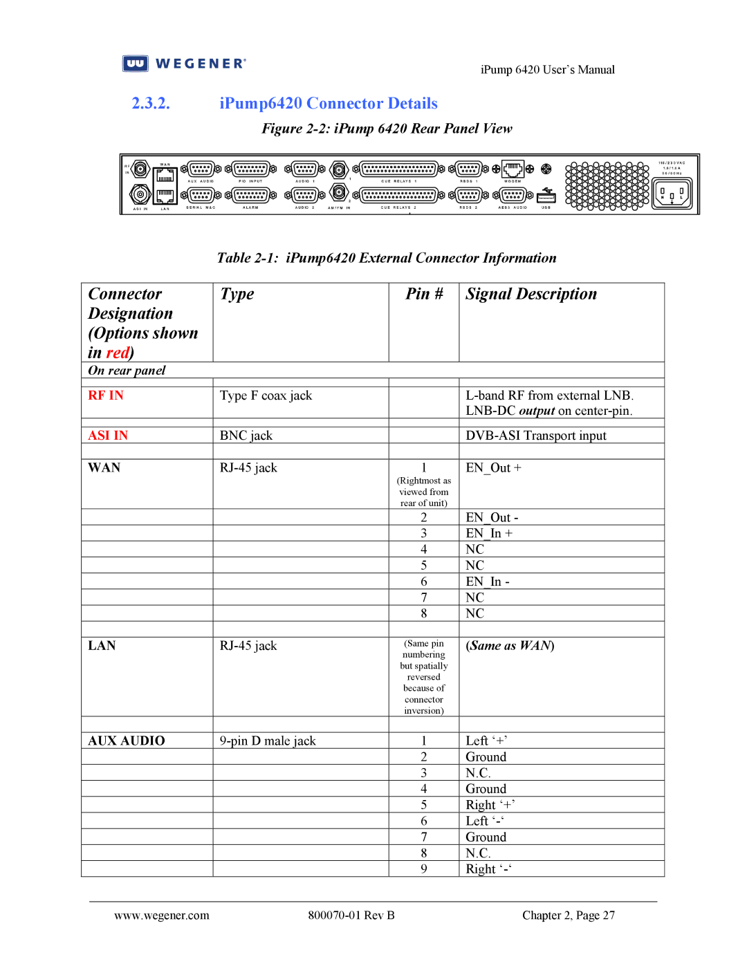
IPump 6420 Rear Panel Connections
Equipment Setup
On rear panel
IPump6420 Connector Details
Serial M&C
Connector Type
Same as CUE Relays
Establishing Compel Network Control
Getting Local Web Control
Check/set RF carrier settings
Setup through the Front-Panel
Check/set LNB LO
Check/set LAN and/or WAN Ethernet port settings
Check/set audio port settings
Check/set Terminal port settings
Front-panel LCD Home Screen
Unit Indications
Glossary of the terms
Front-panel LED Indications
Rev B
Operation
Basic IRD Functions
100
Compel
Monitor & Control Interfaces
In-channel Compel Control
Command Structure
Internet-delivered Compel Control
Timing
Triggers
Local Scheduler
Physical Delivery Methods
Return Path
Report Types
Home Status screen
Local Web
Typical Home Status screen, web interface
Parameter info screen, web interface
Setup screens
Audio Decoder setup screen, web interface
Transport Input, web interface
Expansion Relay screen, web interface
AM/FM tuning screen, web interface
File Manager screen
System screen, web interface
Record/play screen
File Manager screen, web interface
Scheduled Events screen
10 Record/Play screen, web interface
Playlist Builder screen
11 Scheduled Events screen, web interface
ShowShifting screen
12 Playlist Builder screen, web interface
Logs screen
13 ShowShifting initial screen, web interface
14 As-run Log screen, web interface
User Controls
Diagnostic screen
LCD Screen Types
Front-Panel Monitor and Control
LED Indications
LCD Screen Modes
Push Button Definitions
LCD Mode Push LCD Screen Function Button Type
Front-panel Menu structure
Default LCD Screen
Disable
Full ACCESS, Read
Pkts
Terminal
PIO Inputs
Loss-of-Signal
Auto Recovery Modes
Snmp Status
Fault Indications
DVB Tuner
Tuning Parameters
Basic IRD Functions
Transport Front-end
Audio Stream Selection
Live Audio play
LNB DC output
Transport Demux
Audio Buffer delay
Codec, resamplers, timing adjustments buffer-locked loop
Delivery of Relay closures
Audio Settings Muting, Stereo Routing & Attenuation
Basic File and Asset Management
Stored File Creation and Management
Delivery of Rbds data
File Storage and Management database
Automatic File and Asset Deletion
Assured File Delivery over satellite
Kencast File Delivery over satellite
Other file creation & delivery mechanisms
Http File Delivery over internet
Asset Healing, a content modeling & recovery utility
Wegener Asset Healing, an Overview
Simple File inserts
Insertion of Audio from Stored Files
Playlists
Timing Model
17 iPump6420 File Insertion Timing Model
Overview
Insertion Profiles
Current Profile Keywords
Sequential
File Selection Keywords
18 Example of using the Shuffle file selection keyword
Asset Aliases
Off-Air Recording option
Off-Air Capture
1. AM/FM tuner setup
Application Management
Software Upgrade process
Miscellaneous Functions
File Return for Audit
Relevant user controls
Logging
Non-volatile Parameter Management
Master Time Reference
Time Management
Time Zone management
HDD Failure
Premium Features
Microcasting aka Automation Mode
IPump 6420 User’s Manual
19 Automation monitor screen, local web interface
ShowShifting
Setup
Operation
User Indications and controls
ShowShifting authorizing keyfile names
IPump 6420 User’s Manual
20 ShowShift Shift-definition screen, local web interface
Time Zone Delay
New relevant user controls are
4. MP3 Codec
Maintenance 102 Troubleshooting
Maintenance and Troubleshooting
Troubleshooting
Maintenance
Failure to acquire a carrier
Failure to get Compel control over internet
Failure to get Compel control over satellite
Failure to get live audio play on a Decoder output
Failure to get file downloads over internet Http
Failure to get file downloads over satellite
Failure to play file inserts on a Decoder
Failure to get local web connection
Failure to play playlists
Failure to get Return Path reports
Failure to upgrade application software
Customer Service
Technical Support
Warranty
Terminal Command Listing
Appendix 1 Terminal Commands
IPump 6420 User’s Manual
IPump 6420 User’s Manual
IPump 6420 User’s Manual
WEGENER-ROOT-MIB Definitions = Begin
Appendix 2 Snmp Mibs A2.1. Root MIB
A2.2. Pcmi MIB
Syntax Integer
Mavgebno
MMGLITCHESIN5MIN
Commanded1 Lastsuccess253 Perm254 Current255 Temp256
Mdatarate
Mlabel
IPump 6420 User’s Manual
False0 True1
Integer
Table containing Pcmi meta information. = pcmiInfo
IPump 6420 User’s Manual
OBJECT-TYPE
END
This page intentionally left blank
Front Panel Message Possible Cause
Appendix 3 Fault Conditions
Service
Wegener Communications, Inc