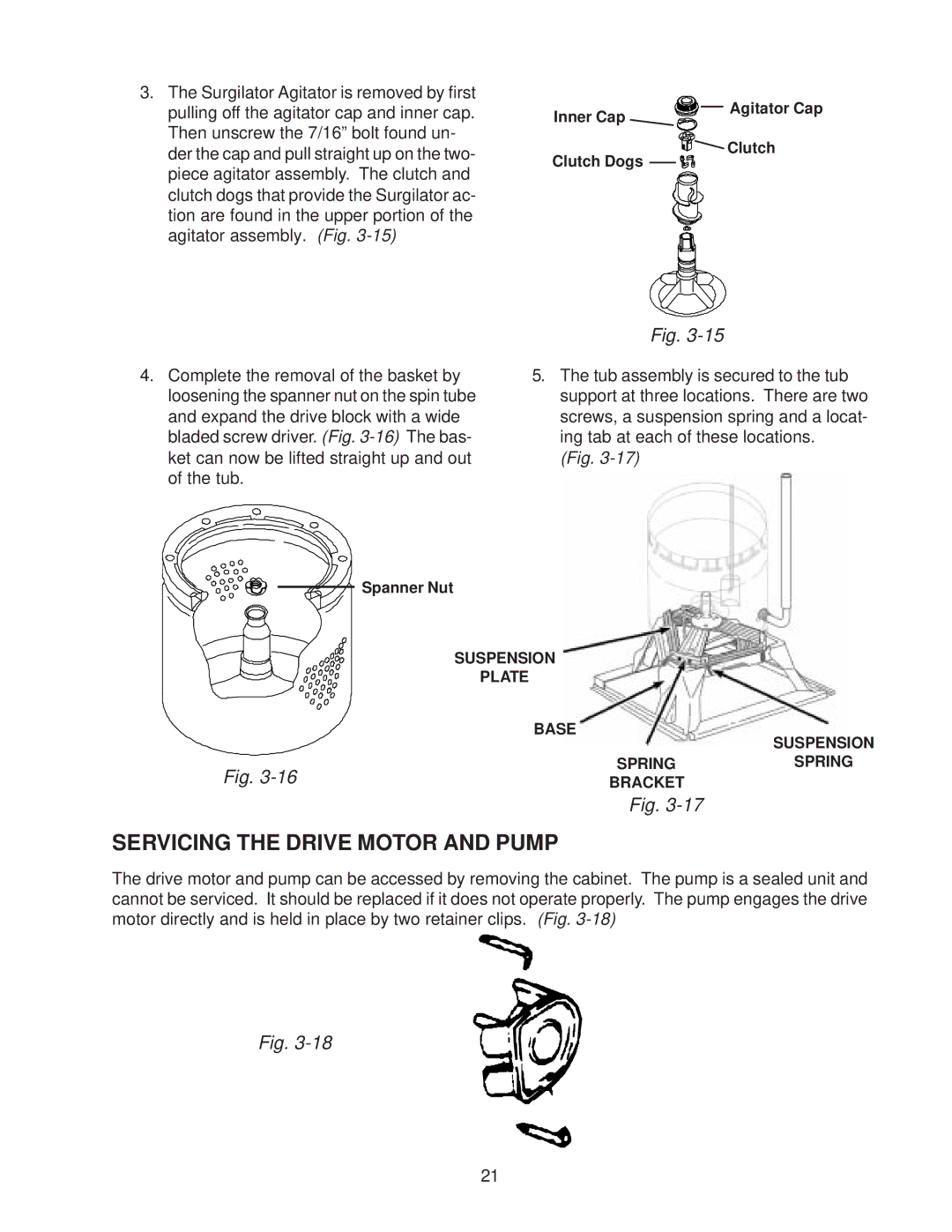
3. The Surgilator Agitator is removed by first |
pulling off the agitator cap and inner cap. |
Then unscrew the 7/16” bolt found un- |
Inner Cap
Agitator Cap
der the cap and pull straight up on the two- |
piece agitator assembly. The clutch and |
clutch dogs that provide the Surgilator ac- |
tion are found in the upper portion of the |
agitator assembly. (Fig. |
Clutch
Clutch Dogs
Fig.
4.Complete the removal of the basket by loosening the spanner nut on the spin tube and expand the drive block with a wide bladed screw driver. (Fig.
5.The tub assembly is secured to the tub support at three locations. There are two screws, a suspension spring and a locat- ing tab at each of these locations.
(Fig.
| Spanner Nut |
|
| SUSPENSION |
|
| PLATE |
|
| BASE | SUSPENSION |
|
| |
Fig. | SPRING | SPRING |
BRACKET |
|
Fig.
SERVICING THE DRIVE MOTOR AND PUMP
The drive motor and pump can be accessed by removing the cabinet. The pump is a sealed unit and cannot be serviced. It should be replaced if it does not operate properly. The pump engages the drive motor directly and is held in place by two retainer clips. (Fig.
Fig.
21