Servicing the Splutch Assembly
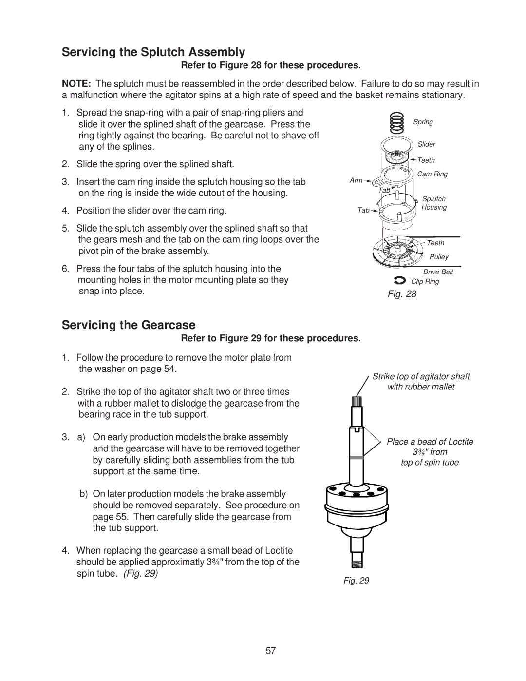
Refer to Figure 28 for these procedures.
NOTE: The splutch must be reassembled in the order described below. Failure to do so may result in a malfunction where the agitator spins at a high rate of speed and the basket remains stationary.
1.Spread the
2.Slide the spring over the splined shaft.
3.Insert the cam ring inside the splutch housing so the tab on the ring is inside the wide cutout of the housing.
4.Position the slider over the cam ring.
5.Slide the splutch assembly over the splined shaft so that the gears mesh and the tab on the cam ring loops over the pivot pin of the brake assembly.
6.Press the four tabs of the splutch housing into the mounting holes in the motor mounting plate so they snap into place.
Spring
Slider
Teeth
Cam Ring
Arm
Tab
Splutch
TabHousing
Teeth
Pulley
Drive Belt
Clip Ring
Fig. 28
Servicing the Gearcase
Refer to Figure 29 for these procedures.
1.Follow the procedure to remove the motor plate from the washer on page 54.
2. Strike the top of the agitator shaft two or three times with a rubber mallet to dislodge the gearcase from the bearing race in the tub support.
Strike top of agitator shaft
with rubber mallet
3.a) On early production models the brake assembly and the gearcase will have to be removed together by carefully sliding both assemblies from the tub support at the same time.
b)On later production models the brake assembly should be removed separately. See procedure on page 55. Then carefully slide the gearcase from the tub support.
4.When replacing the gearcase a small bead of Loctite should be applied approximatly 3¾" from the top of the spin tube. (Fig. 29)
Place a bead of Loctite
3¾" from top of spin tube
Fig. 29
57