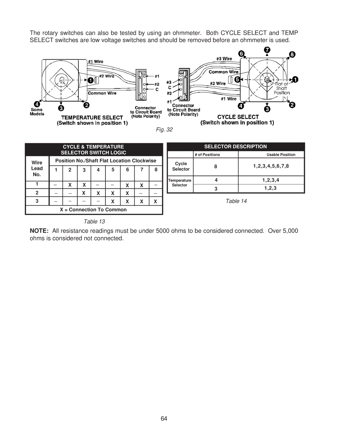
The rotary switches can also be tested by using an ohmmeter. Both CYCLE SELECT and TEMP SELECT switches are low voltage switches and should be removed before an ohmmeter is used.
Fig. 32
CYCLE & TEMPERATURE
SELECTOR SWITCH LOGIC
Wire | Position No./Shaft Flat Location Clockwise | |||||||
|
|
|
|
|
|
|
| |
Lead | 1 | 2 | 3 | 4 | 5 | 6 | 7 | 8 |
No. |
|
|
|
|
|
|
|
|
1 | _ | X | X | _ | _ | X | X | _ |
2 | _ | _ | X | X | X | X | _ | _ |
|
|
|
| |||||
3 | _ | _ | _ | _ | X | X | X | X |
|
|
|
| |||||
|
|
|
|
|
|
|
|
|
X = Connection To Common
SELECTOR DESCRIPTION
| # of Positions | Usable Position | |
|
|
|
|
Cycle | 8 | 1,2,3,4,5,6,7,8 |
|
Selector |
| ||
|
|
| |
|
|
|
|
Temperature | 4 | 1,2,3,4 |
|
Selector |
|
|
|
3 | 1,2,3 |
| |
|
| ||
Table 14
Table 13
NOTE: All resistance readings must be under 5000 ohms to be considered connected. Over 5,000 ohms is considered not connected.
64
