Spin Cycle
NOTE: See SPIN Strip Circuit on page 68.
The drain pump and brake solenoid are energized at the beginning of the Spin Cycle. The energized brake solenoid releases the brake and engages the splutch.
For the first 120 seconds of the Spin Cycle the electronic control board sequentially cycles the drive motor on and off to allow the basket to slowly build up speed. This
Table 6
Spin Start Up Sequence (S.I.S.)
Cycle Duration | Duration of Rotation |
OFF | 45 sec. |
ON | 3 sec. |
OFF | 14 sec. |
ON | 20 sec. |
OFF | 8 sec. |
ON | 20 sec. |
OFF | 10 sec. |
ON | Remainder of Spin Cycle |
|
|
Heavy Duty and Normal Rinse Cycle Spin: S.I.S. runs for 120 seconds.
Permanent Press and Gentle Cycle Spin: S.I.S. runs through entire spin.
The Splutch Assembly
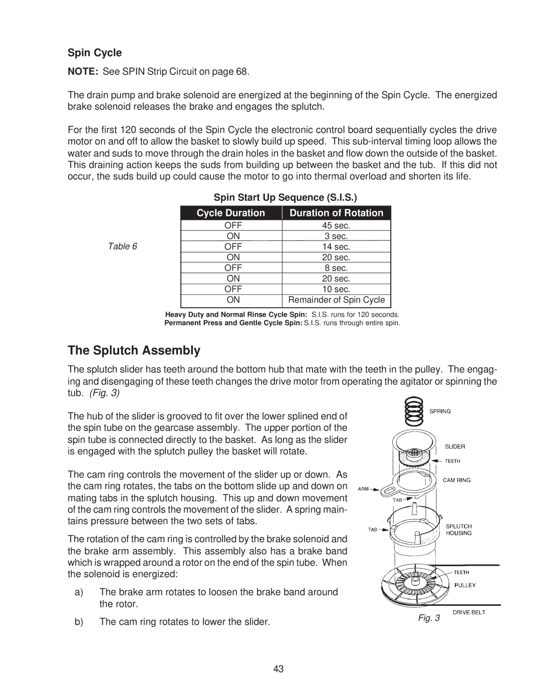
The splutch slider has teeth around the bottom hub that mate with the teeth in the pulley. The engag- ing and disengaging of these teeth changes the drive motor from operating the agitator or spinning the tub. (Fig. 3)
The hub of the slider is grooved to fit over the lower splined end of the spin tube on the gearcase assembly. The upper portion of the spin tube is connected directly to the basket. As long as the slider is engaged with the splutch pulley the basket will rotate.
The cam ring controls the movement of the slider up or down. As the cam ring rotates, the tabs on the bottom slide up and down on mating tabs in the splutch housing. This up and down movement of the cam ring controls the movement of the slider. A spring main- tains pressure between the two sets of tabs.
The rotation of the cam ring is controlled by the brake solenoid and the brake arm assembly. This assembly also has a brake band which is wrapped around a rotor on the end of the spin tube. When the solenoid is energized:
a)The brake arm rotates to loosen the brake band around the rotor.
b) The cam ring rotates to lower the slider. | Fig. 3 |
|
43