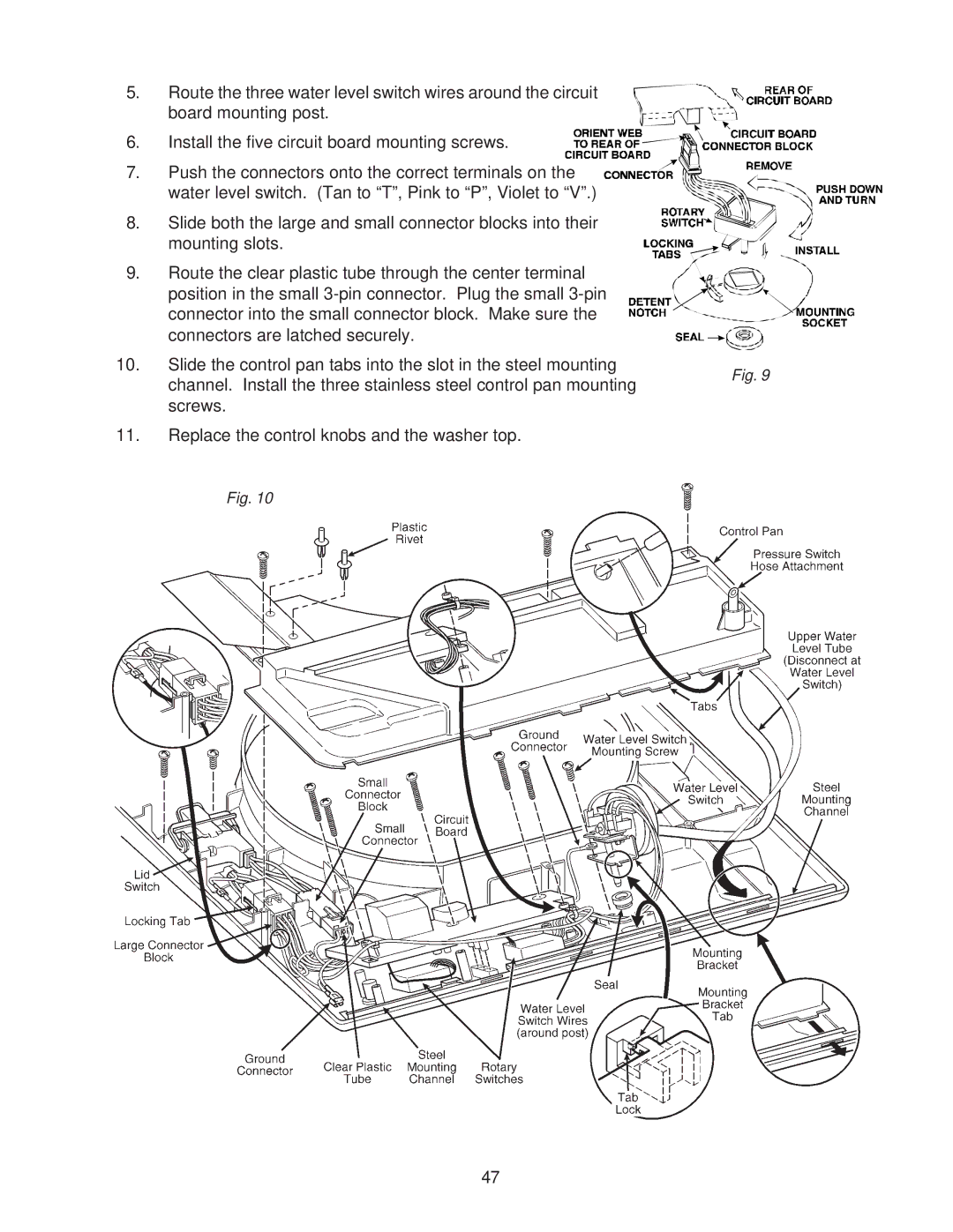
5. Route the three water level switch wires around the circuit board mounting post.
6. Install the five circuit board mounting screws.
7. Push the connectors onto the correct terminals on the water level switch. (Tan to “T”, Pink to “P”, Violet to “V”.)
8. Slide both the large and small connector blocks into their mounting slots.
9. Route the clear plastic tube through the center terminal position in the small
10. Slide the control pan tabs into the slot in the steel mounting
Fig. 9
channel. Install the three stainless steel control pan mounting screws.
11.Replace the control knobs and the washer top.
Fig. 10
47