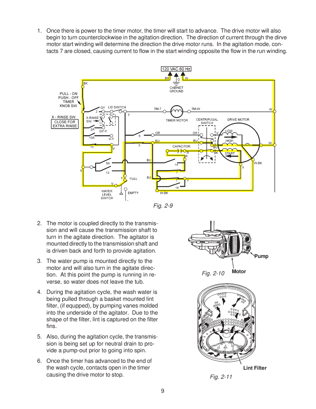
1.Once there is power to the timer motor, the timer will start to advance. The drive motor will also begin to turn counterclockwise in the agitation direction. The direction of current through the dirve motor start winding will determine the direction the drive motor runs. In the agitation mode, con- tacts 7 are closed, causing current to flow in the start winding opposite the flow in the run winding.
Fig.
2.The motor is coupled directly to the transmis- sion and will cause the transmission shaft to turn in the agitate direction. The agitator is mounted directly to the transmission shaft and is driven back and forth to provide agitation.
3.The water pump is mounted directly to the motor and will also turn in the agitate direc- tion. At this point the pump is running in re- verse, so water does not leave the tub.
4.During the agitation cycle, the wash water is being pulled through a basket mounted lint filter, (if equpped), by pumping vanes molded into the underside of the agitator. Due to the shape of the filter, lint is captured on the filter fins.
5.Also, during the agitation cycle, the transmis- sion is being set up for neutral drain to pro- vide a
6.Once the timer has advanced to the end of the wash cycle, contacts open in the timer causing the drive motor to stop.
Pump
Fig. | Motor |
|
Lint Filter
Fig.
9