The water level switch is set to move from the EMPTY position to the FULL position depend- ing on how much tension is set on the switch diaphragm.
3. When the customer pulls the timer knob out, |
voltage is supplied to the hot and/or cold wa- |
ter inlet solenoids. In the example above, both |
solenoids are energized to allow water to fill |
the tub. |
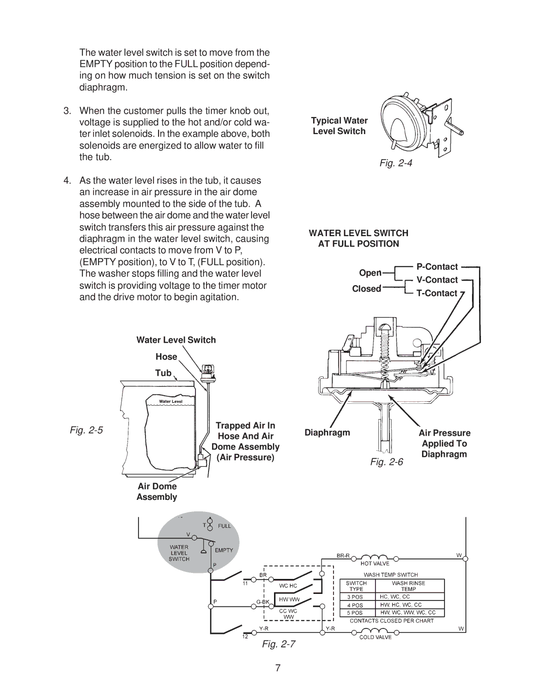
4. As the water level rises in the tub, it causes |
an increase in air pressure in the air dome |
assembly mounted to the side of the tub. A |
hose between the air dome and the water level |
switch transfers this air pressure against the |
diaphragm in the water level switch, causing |
electrical contacts to move from V to P, |
(EMPTY position), to V to T, (FULL position). |
Typical Water
Level Switch
Fig.
WATER LEVEL SWITCH
AT FULL POSITION
The washer stops filling and the water level |
switch is providing voltage to the timer motor |
Open
and the drive motor to begin agitation. |
Water Level Switch
Hose
Tub
Fig. | Trapped Air In | |
Hose And Air | ||
| ||
| Dome Assembly | |
| (Air Pressure) | |
| Air Dome | |
| Assembly |
Fig.
Closed
Diaphragm | Air Pressure |
| Applied To |
| Diaphragm |
Fig.
7