Removing the Timer
1.Pull the timer knob off the timer assembly shaft.
2.Tip the console into the service position.
3.Disconnect the wiring harness connectors from the timer assembly terminals.
4.Remove the two (2) screws securing the timer assembly mounting bracket to the console.
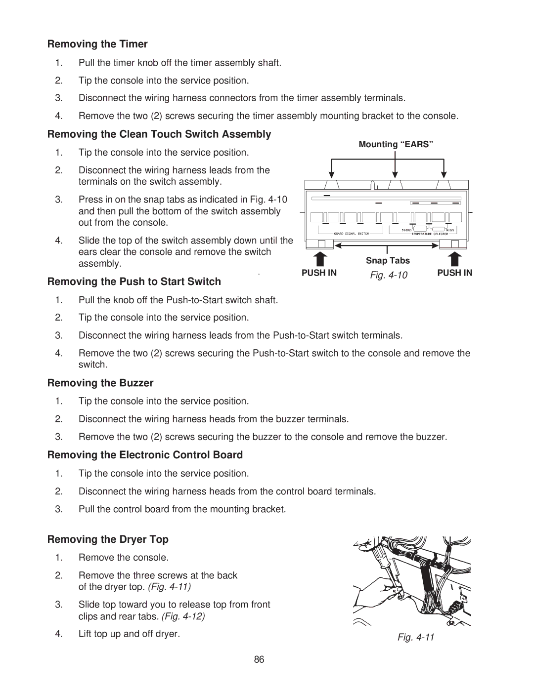
Removing the Clean Touch Switch Assembly
1.Tip the console into the service position.
2.Disconnect the wiring harness leads from the terminals on the switch assembly.
3.Press in on the snap tabs as indicated in Fig.
4.Slide the top of the switch assembly down until the ears clear the console and remove the switch assembly.
Mounting “EARS”
Snap Tabs
.
PUSH INPUSH IN
Removing the Push to Start Switch
Fig.
1.Pull the knob off the
2.Tip the console into the service position.
3.Disconnect the wiring harness leads from the
4.Remove the two (2) screws securing the
Removing the Buzzer
1.Tip the console into the service position.
2.Disconnect the wiring harness heads from the buzzer terminals.
3.Remove the two (2) screws securing the buzzer to the console and remove the buzzer.
Removing the Electronic Control Board
1.Tip the console into the service position.
2.Disconnect the wiring harness heads from the control board terminals.
3.Pull the control board from the mounting bracket.
Removing the Dryer Top
1.Remove the console.
2.Remove the three screws at the back of the dryer top. (Fig.
3.Slide top toward you to release top from front clips and rear tabs. (Fig.
4. Lift top up and off dryer. | Fig. |
|
86