TEST #2: MOTOR CIRCUIT TEST
This test will check the wiring to the motor and the motor itself. The following items are part of this system:
•Harness/connection
•Thermal fuse (electric dryers only)
•Belt/belt switch
•Drive motor
•Door switch
•Electronic control board
1.Unplug dryer or disconnect power.
2.Access the electronic control board and measure the resistance across
•If resistance across
•Otherwise, go to step 3.
3.Check the wiring and components in the path between these measurement points (refer to the Wiring Diagrams in Section 7).
4.Electric Dryers Only: Check the thermal fuse (see TEST #3b on page
5.Check the belt switch and drive motor.
Belt Switch Pulley
Drum Belt
6.Remove the white connector from the drive motor switch.
Drive Motor Switch
White Connector
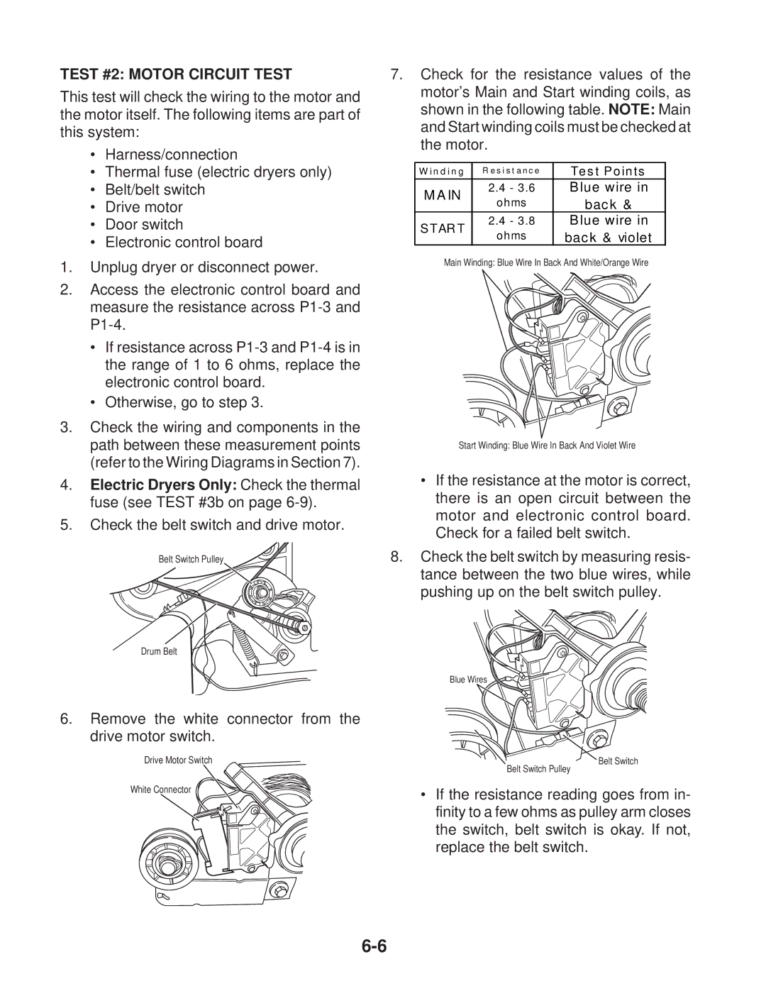
7.Check for the resistance values of the motor’s Main and Start winding coils, as shown in the following table. NOTE: Main and Start winding coils must be checked at the motor.
W inding | R e s i s t a nc e | Tes t Points | |
MA IN | 2.4 - 3.6 | Blue wire in | |
ohms | back & | ||
| |||
S T AR T | 2.4 - 3.8 | Blue wire in | |
ohms | back & violet | ||
|
Main Winding: Blue Wire In Back And White/Orange Wire
Start Winding: Blue Wire In Back And Violet Wire
•If the resistance at the motor is correct, there is an open circuit between the motor and electronic control board. Check for a failed belt switch.
8.Check the belt switch by measuring resis- tance between the two blue wires, while pushing up on the belt switch pulley.
Blue Wires
Belt Switch
Belt Switch Pulley
•If the resistance reading goes from in- finity to a few ohms as pulley arm closes the switch, belt switch is okay. If not, replace the belt switch.