8.Remove the following connectors and wires from the electronic control board:
Red and black wires at relay K1.
Ribbon cables at P3 and P4.
P1 | Relay K1 P2 |
Electronic Control
Board
1/4 inch Screw | Ribbon Cables | |
| P3 & P4 | Connector |
9.Remove the 1/4 inch
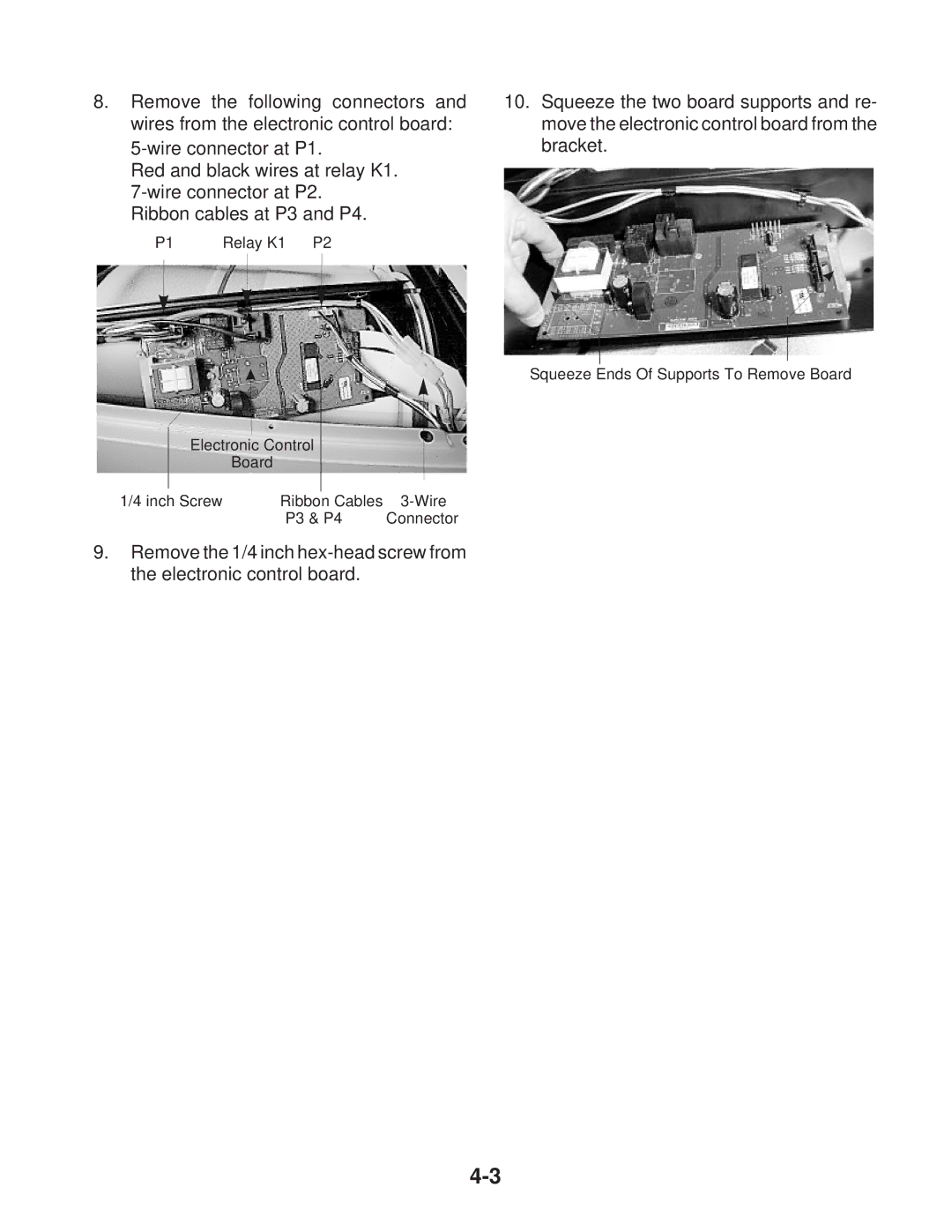
10.Squeeze the two board supports and re- move the electronic control board from the bracket.
Squeeze Ends Of Supports To Remove Board