![]() WARNING
WARNING
Electrical Shock Hazard
Disconnect power before servicing.
Replace all parts and panels before operating.
Failure to do so can result in death or electrical shock.
Resistance Tests
Refer to page | 1. | Unplug dryer or disconnect power. | ||||
ing the door switch. | 2. | Turn off gas supply to dryer. | ||||
1. Go into the Diagnostic Test mode on page 6- | ||||||
3. | Close the dryer door. | |||||
2. The door switch function is verified with | ||||||
4. | Disconnect the | |||||
a beep each time the door is opened and | ||||||
| door switch to the electronic control board. | |||||
closed, and an alpha numeric code ap- |
| |||||
5. | Set the ohmmeter to the R X 1 scale. | |||||
pears in the display (“0E”, “0g”, “1E”, or | ||||||
Refer to the illustration below for the following | ||||||
“2E”). |
|
|
| |||
2. If any of the conditions are not met, or if | tests. | |||||
6. | Touch the black ohmmeter test lead to the | |||||
one of the dryer model codes listed above | ||||||
is displayed when the door is closed, check |
| white wire pin in the connector and leave | ||||
| it there for the remaining tests. | |||||
that the wires between the door switch and |
| |||||
7. | Touch the red ohmmeter test lead to the | |||||
the electronic control board are properly | ||||||
connected. |
|
|
|
| brown wire pin in the connector. The meter | |
If the wiring is okay, perform the resistance |
| should indicate an open circuit (infinite). | ||||
8. | Touch the red ohmmeter test lead to the | |||||
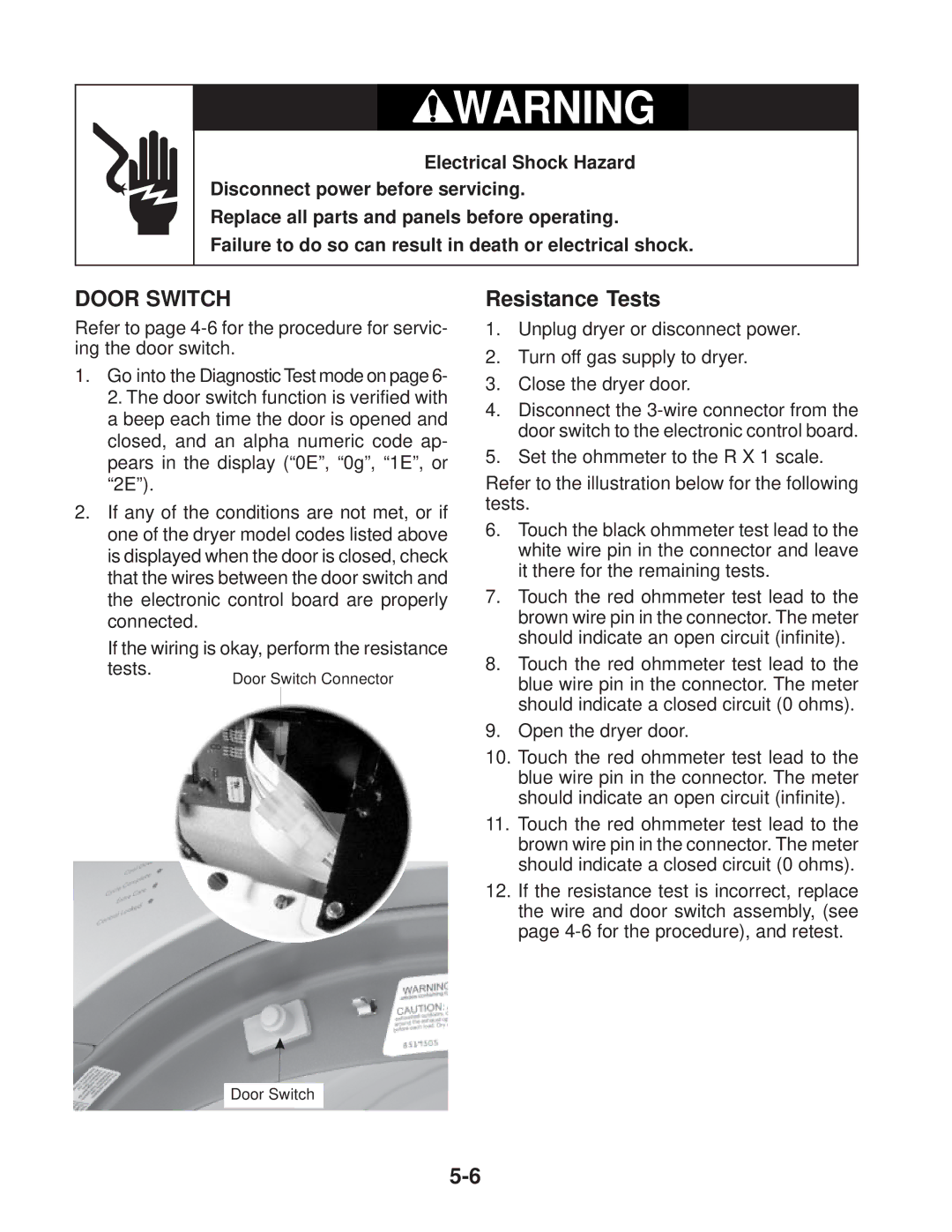
tests. | Door |
| Switch Connector | |||
|
|
| blue wire pin in the connector. The meter | |||
|
|
| ||||
|
|
|
|
| should indicate a closed circuit (0 ohms). | |
|
|
|
| 9. | Open the dryer door. | |
|
|
|
| 10. | Touch the red ohmmeter test lead to the | |
|
|
|
|
| blue wire pin in the connector. The meter | |
|
|
|
|
| should indicate an open circuit (infinite). | |
|
|
|
| 11. | Touch the red ohmmeter test lead to the | |
|
|
|
|
| brown wire pin in the connector. The meter | |
|
|
|
|
| should indicate a closed circuit (0 ohms). | |
|
|
|
| 12. | If the resistance test is incorrect, replace | |
|
|
|
|
| the wire and door switch assembly, (see | |
|
|
|
|
| page | |