Checking The Rotary Cycle Selector
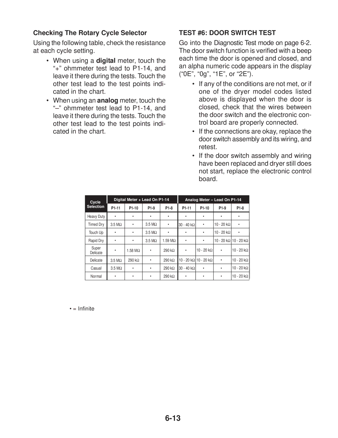
Using the following table, check the resistance at each cycle setting.
•When using a digital meter, touch the “+” ohmmeter test lead to
•When using an analog meter, touch the
TEST #6: DOOR SWITCH TEST
Go into the Diagnostic Test mode on page
•If any of the conditions are not met, or if one of the dryer model codes listed above is displayed when the door is closed, check that the wires between the door switch and the electronic con- trol board are properly connected.
•If the connections are okay, replace the door switch assembly and its wiring, and retest.
•If the door switch assembly and wiring have been replaced and dryer still does not start, replace the electronic control board.
Cycle | Digital Meter + Lead On | Analog Meter – Lead On | ||||||||
|
|
|
|
|
|
|
|
|
| |
Selection |
|
| ||||||||
|
| |||||||||
|
|
|
|
|
|
|
|
|
|
|
Heavy Duty | • | • |
| • | • | • | • |
| • | • |
|
|
|
|
|
|
|
|
|
|
|
Timed Dry | 3.5 MΩ | • |
| 3.5 MΩ | • | 30 - 40 kΩ | • | 10 | - 20 kΩ | • |
|
|
|
|
|
|
|
|
|
|
|
Touch Up | • | • |
| 3.5 MΩ | • | • | • | 10 | - 20 kΩ | • |
|
|
|
|
|
|
|
|
|
|
|
Rapid Dry | • | • |
| 3.5 MΩ | 1.59 MΩ | • | • | 10 | - 20 kΩ | 10 - 20 kΩ |
|
|
|
|
|
|
|
|
|
|
|
Super | • | 1.58 | MΩ | • | 290 kΩ | • | 10 - 20 kΩ |
| • | 10 - 20 kΩ |
Delicate |
| |||||||||
|
|
|
|
|
|
|
|
|
| |
Delicate | 3.5 MΩ | 290 kΩ | • | 290 kΩ | 10 - 20 kΩ | 10 - 20 kΩ |
| • | 10 - 20 kΩ | |
|
|
|
|
|
|
|
|
|
|
|
Casual | 3.5 MΩ | • |
| • | 290 kΩ | 30 - 40 kΩ | • |
| • | 10 - 20 kΩ |
|
|
|
|
|
|
|
|
|
|
|
Normal | • | • |
| • | 290 kΩ | • | • |
| • | 10 - 20 kΩ |
|
|
|
|
|
|
|
|
|
|
|
• = Infinite