Checking The Button Functions
Before replacing the electronic control board, check for proper button function as follows:
•Unplug dryer or disconnect power.
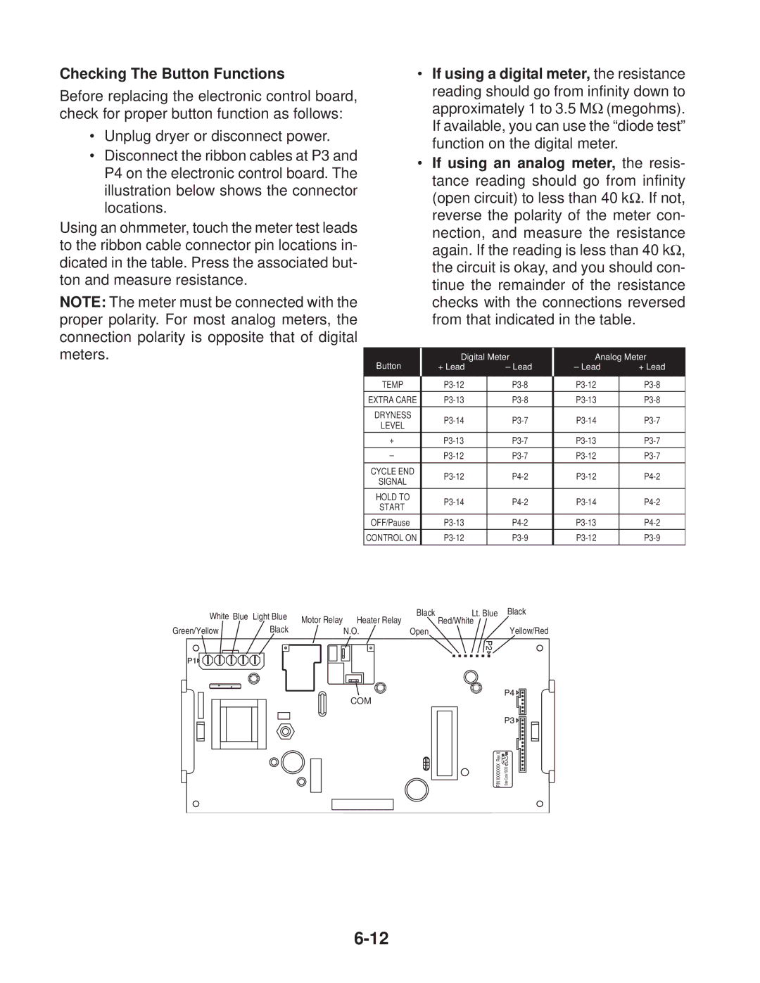
•Disconnect the ribbon cables at P3 and P4 on the electronic control board. The illustration below shows the connector locations.
Using an ohmmeter, touch the meter test leads to the ribbon cable connector pin locations in- dicated in the table. Press the associated but- ton and measure resistance.
NOTE: The meter must be connected with the proper polarity. For most analog meters, the connection polarity is opposite that of digital meters.
•If using a digital meter, the resistance
reading should go from infinity down to approximately 1 to 3.5 MΩ (megohms). If available, you can use the “diode test” function on the digital meter.
•If using an analog meter, the resis-
tance reading should go from infinity (open circuit) to less than 40 kΩ. If not, reverse the polarity of the meter con-
nection, and measure the resistance again. If the reading is less than 40 kΩ, the circuit is okay, and you should con- tinue the remainder of the resistance checks with the connections reversed from that indicated in the table.
Button | Digital | Meter | Analog | Meter | |
+ Lead | – Lead | – Lead | + Lead | ||
|
|
|
|
| |
TEMP | |||||
EXTRA CARE | |||||
|
|
|
|
| |
DRYNESS | |||||
LEVEL | |||||
|
|
|
| ||
+ | |||||
– | |||||
|
|
|
|
| |
CYCLE END | |||||
SIGNAL | |||||
|
|
|
| ||
HOLD TO | |||||
START | |||||
|
|
|
| ||
OFF/Pause | |||||
CONTROL ON | |||||
|
|
|
|
|
White Blue | Light Blue | Motor Relay | Heater Relay | Black | Lt. Blue Black |
| Red/White | ||||
Green/Yellow | Black |
| |||
| N.O. | Open | Yellow/Red |
COM
Rev X |
|
XXXXXXX | Code YDDD |
P/N | Date |
