![]() WARNING
WARNING
Electrical Shock Hazard
Disconnect power before servicing.
Replace all parts and panels before operating.
Failure to do so can result in death or electrical shock.
GAS BURNER COILS
Refer to page
1.Unplug dryer or disconnect power.
2.Turn off gas supply to dryer.
3.Disconnect the wire connectors from the coil terminals.
4.Set the ohmmeter to the R X 100 scale.
5.Touch the ohmmeter test leads to the
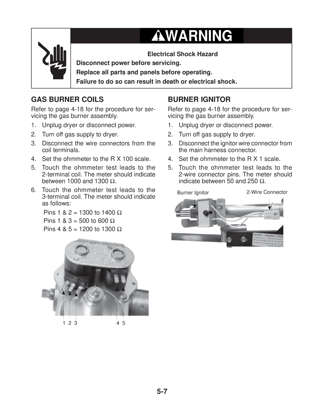
6.Touch the ohmmeter test leads to the
Pins 1 & 2 = 1300 to 1400 Ω
Pins 1 & 3 = 500 to 600 Ω
Pins 4 & 5 = 1200 to 1300 Ω
BURNER IGNITOR
Refer to page
1.Unplug dryer or disconnect power.
2.Turn off gas supply to dryer.
3.Disconnect the ignitor wire connector from the main harness connector.
4.Set the ohmmeter to the R X 1 scale.
5.Touch the ohmmeter test leads to the
Burner Ignitor |
1 | 2 | 3 | 4 | 5 |