4.If E1 or E2 does not flash in the display, the connections to the thermistor are good. Therefore, check the thermistor’s resis- tance value at any or all of the temperature levels in question, using the Timed Dry Cycle, and the following process:
Hold a glass bulb thermometer capable of reading from 32⋅ to 82⋅C (90⋅ to 180⋅F) in the center of the exhaust outlet. The fol- lowing table shows the correct exhaust temperatures.
|
| Thermistor resistance | ||
TEMP. | TEMPERATURE | value at heater | ||
SETTING | shutoff (digital or | |||
|
| analog meter) kΩ | ||
|
|
|
| |
High | 155° ± 10°F | 2.5 | 1.5 | |
(68° ± 6°C) | ||||
|
|
| ||
Medium | 140° ± 10°F | 4.0 | 3.0 | |
(60° ± 6°C) | ||||
|
|
| ||
Low | 125° ± 10°F | 5 | 4.3 | |
(52° ± 6°C) | ||||
|
|
| ||
Extra Low | 105° ± 5°F | 6 | 5 | |
(41° ± 3°C) | ||||
|
|
| ||
5.If the exhaust temperature is not within specified limits, use the following table, and check the resistance of the thermistor.
THERMISTOR RESISTANCE
TEMP. | RES. | TEMP. | RES. |
°C (°F) | k Ω | °C (°F) | k Ω |
|
|
|
|
10° (50°) | 19.9 | 27° (80°) | 9.2 |
|
|
|
|
16° (60°) | 15.3 | 32° (90°) | 7.4 |
|
|
|
|
21° (70°) | 11.9 | 38° (100°) | 5.7 |
|
|
|
|
TEST #3b: THERMAL FUSE TEST
1.Unplug dryer or disconnect power.
2.Access the thermal fuse by first removing the toe panel.
•Gas Dryers Only: The thermal fuse is wired in series with the dryer gas valve. If the thermal fuse is open, replace it.
•Electric Dryers Only: The thermal fuse is wired in series with the dryer drive motor. If the thermal fuse is open, re- place it.
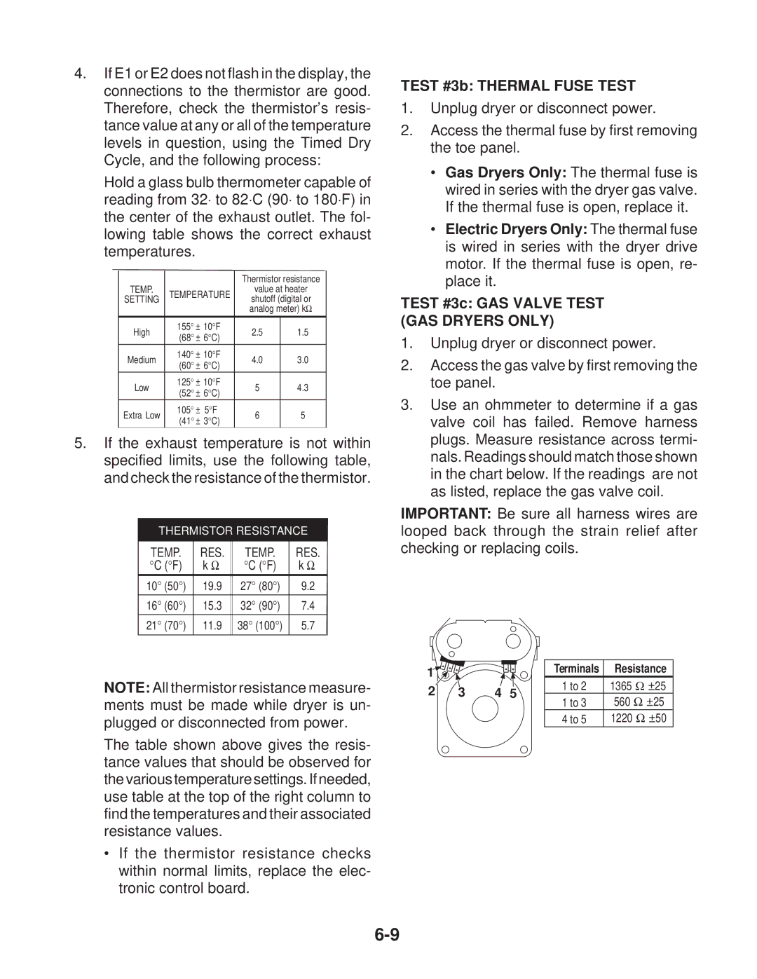
TEST #3c: GAS VALVE TEST (GAS DRYERS ONLY)
1.Unplug dryer or disconnect power.
2.Access the gas valve by first removing the toe panel.
3.Use an ohmmeter to determine if a gas valve coil has failed. Remove harness plugs. Measure resistance across termi- nals. Readings should match those shown in the chart below. If the readings are not as listed, replace the gas valve coil.
IMPORTANT: Be sure all harness wires are looped back through the strain relief after checking or replacing coils.
NOTE: All thermistor resistance measure- ments must be made while dryer is un- plugged or disconnected from power.
The table shown above gives the resis- tance values that should be observed for the various temperature settings. If needed, use table at the top of the right column to find the temperatures and their associated resistance values.
•If the thermistor resistance checks within normal limits, replace the elec- tronic control board.
1 |
|
|
|
2 | 3 | 4 | 5 |
Terminals | Resistance |
1 to 2 | 1365 Ω ±25 |
1 to 3 | 560 Ω ±25 |
4 to 5 | 1220 Ω ±50 |