Chapter 1: SP601 Evaluation Board
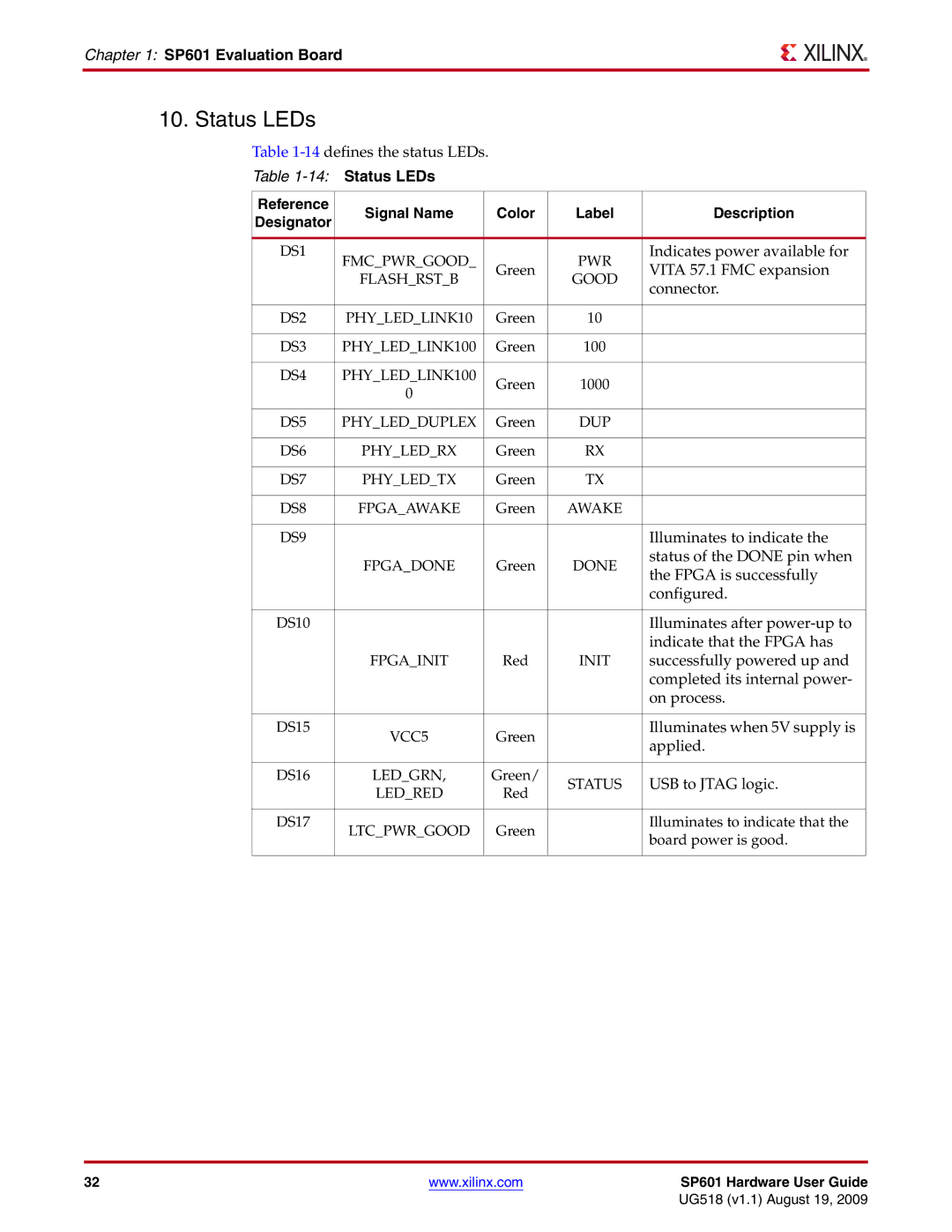
10. Status LEDs
Table
Table
Reference | Signal Name | Color | Label | Description | |
Designator | |||||
|
|
|
| ||
|
|
|
|
| |
DS1 | FMC_PWR_GOOD_ |
| PWR | Indicates power available for | |
| Green | VITA 57.1 FMC expansion | |||
| FLASH_RST_B | GOOD | |||
|
| connector. | |||
|
|
|
| ||
|
|
|
|
| |
DS2 | PHY_LED_LINK10 | Green | 10 |
| |
|
|
|
|
| |
DS3 | PHY_LED_LINK100 | Green | 100 |
| |
|
|
|
|
| |
DS4 | PHY_LED_LINK100 | Green | 1000 |
| |
| 0 |
| |||
|
|
|
| ||
|
|
|
|
| |
DS5 | PHY_LED_DUPLEX | Green | DUP |
| |
|
|
|
|
| |
DS6 | PHY_LED_RX | Green | RX |
| |
|
|
|
|
| |
DS7 | PHY_LED_TX | Green | TX |
| |
|
|
|
|
| |
DS8 | FPGA_AWAKE | Green | AWAKE |
| |
|
|
|
|
| |
DS9 |
|
|
| Illuminates to indicate the | |
| FPGA_DONE | Green | DONE | status of the DONE pin when | |
| the FPGA is successfully | ||||
|
|
|
| ||
|
|
|
| configured. | |
|
|
|
|
| |
DS10 |
|
|
| Illuminates after | |
|
|
|
| indicate that the FPGA has | |
| FPGA_INIT | Red | INIT | successfully powered up and | |
|
|
|
| completed its internal power- | |
|
|
|
| on process. | |
|
|
|
|
| |
DS15 | VCC5 | Green |
| Illuminates when 5V supply is | |
|
| applied. | |||
|
|
|
| ||
|
|
|
|
| |
DS16 | LED_GRN, | Green/ | STATUS | USB to JTAG logic. | |
| LED_RED | Red | |||
|
|
| |||
|
|
|
|
| |
DS17 | LTC_PWR_GOOD | Green |
| Illuminates to indicate that the | |
|
| board power is good. | |||
|
|
|
| ||
|
|
|
|
|
32 | www.xilinx.com | SP601 Hardware User Guide |
|
| UG518 (v1.1) August 19, 2009 |
