Detailed Description
User Pushbutton Switches
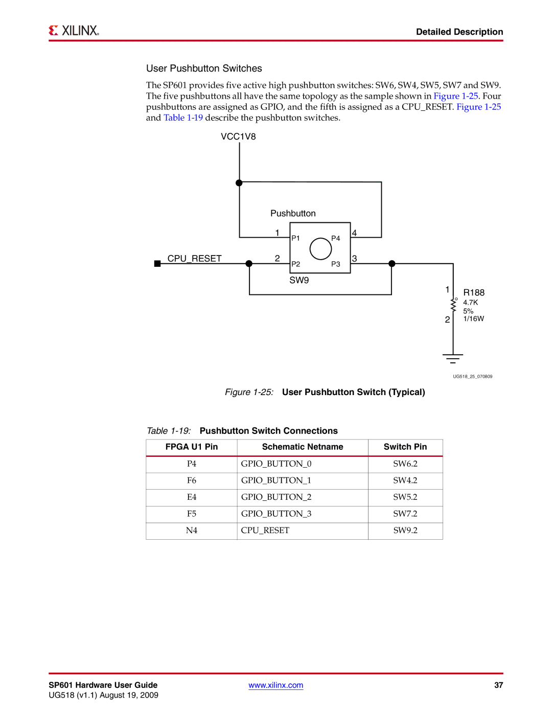
The SP601 provides five active high pushbutton switches: SW6, SW4, SW5, SW7 and SW9. The five pushbuttons all have the same topology as the sample shown in Figure
VCC1V8
Pushbutton
1
CPU_RESET2
P1 P4
P2 P3
4
3
SW9
1 R188
4.7K
5%
2 1/16W
UG518_25_070809
Figure 1-25: User Pushbutton Switch (Typical)
Table 1-19: Pushbutton Switch Connections
FPGA U1 Pin | Schematic Netname | Switch Pin |
|
|
|
P4 | GPIO_BUTTON_0 | SW6.2 |
|
|
|
F6 | GPIO_BUTTON_1 | SW4.2 |
|
|
|
E4 | GPIO_BUTTON_2 | SW5.2 |
|
|
|
F5 | GPIO_BUTTON_3 | SW7.2 |
|
|
|
N4 | CPU_RESET | SW9.2 |
|
|
|
SP601 Hardware User Guide | www.xilinx.com | 37 |
UG518 (v1.1) August 19, 2009