Chapter 1: SP601 Evaluation Board
12. FPGA INIT and DONE LEDs
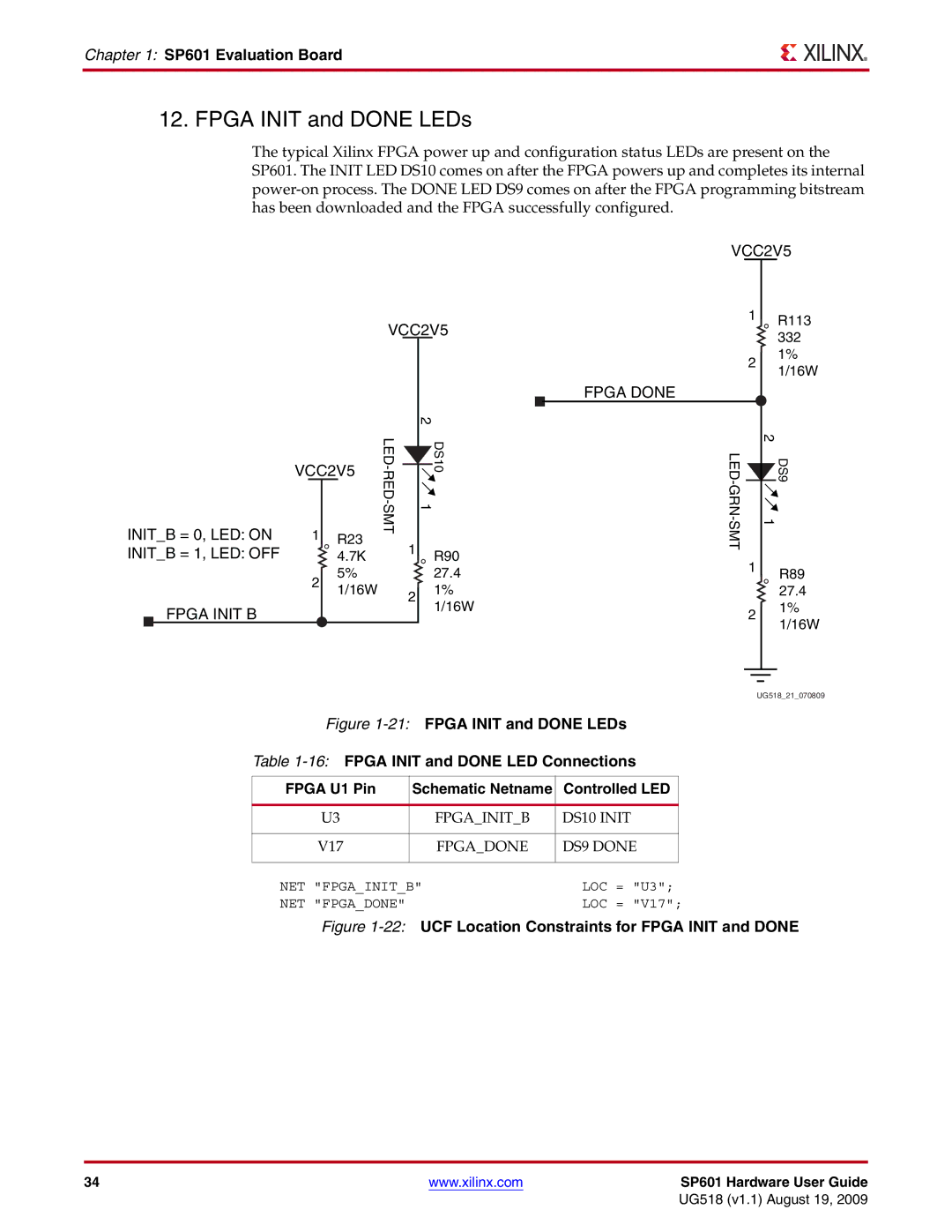
The typical Xilinx FPGA power up and configuration status LEDs are present on the SP601. The INIT LED DS10 comes on after the FPGA powers up and completes its internal
VCC2V5
1 R113
VCC2V5332
2
1%
1/16W
INIT_B = 0, LED: ON
INIT_B = 1, LED: OFF
FPGA INIT B
VCC2V5
1R23
4.7K
5%
21/16W
|
| 2 |
|
| FPGA DONE |
|
|
|
|
|
|
|
| ||
|
|
|
|
|
|
|
|
|
|
|
|
|
| ||
|
|
|
|
|
|
|
|
|
|
|
|
|
| ||
|
|
| DS10 |
|
|
|
| 2 |
| DS9 | |||||
|
| 1 |
|
|
|
|
|
|
| ||||||
1 |
|
|
|
|
| 1 | |||||||||
|
|
| R90 |
|
|
|
|
|
|
|
|
|
|
| |
|
|
|
|
|
|
| 1 |
|
|
|
|
|
| ||
|
| 27.4 |
|
|
|
|
|
|
|
| R89 | ||||
|
|
|
|
|
|
|
|
|
|
|
| ||||
| 2 |
| 1% |
|
|
|
|
|
| 27.4 | |||||
|
|
|
|
|
|
|
| ||||||||
|
|
| 1/16W |
|
|
|
|
|
| 1% | |||||
|
|
|
|
|
|
| 2 |
| |||||||
|
|
|
|
|
|
|
|
|
|
|
|
| 1/16W | ||
|
|
|
|
|
|
|
|
|
|
|
|
|
|
| |
|
|
|
|
|
|
|
|
|
|
|
|
|
|
|
|
|
|
|
|
|
|
|
|
|
|
|
|
|
|
|
|
|
|
|
|
|
|
|
|
|
|
|
|
|
|
|
|
UG518_21_070809
Figure 1-21: FPGA INIT and DONE LEDs
Table 1-16: FPGA INIT and DONE LED Connections
FPGA U1 Pin | Schematic Netname | Controlled LED |
| ||
|
|
|
| ||
U3 | FPGA_INIT_B | DS10 INIT |
| ||
|
|
|
| ||
V17 | FPGA_DONE | DS9 DONE |
| ||
|
|
|
|
|
|
NET "FPGA_INIT_B" | LOC | = | "U3"; | ||
NET "FPGA_DONE" |
| LOC | = | "V17"; | |
Figure 1-22: UCF Location Constraints for FPGA INIT and DONE
34 | www.xilinx.com | SP601 Hardware User Guide |
|
| UG518 (v1.1) August 19, 2009 |