Chapter 1: SP601 Evaluation Board
References
Technical information on the Silicon Labs CP2103GM and the VCP drivers can be found on their website at https://www.silabs.com/Pages/default.aspx.
In addition, see some of the Xilinx UART IP specifications at:
•http://www.xilinx.com/support/documentation/ip_documentation/opb_uartlite.pdf
•http://www.xilinx.com/support/documentation/ip_documentation/xps_uartlite.pdf
•http://www.xilinx.com/support/documentation/ip_documentation/xps_uart16550.pdf
7.IIC Bus
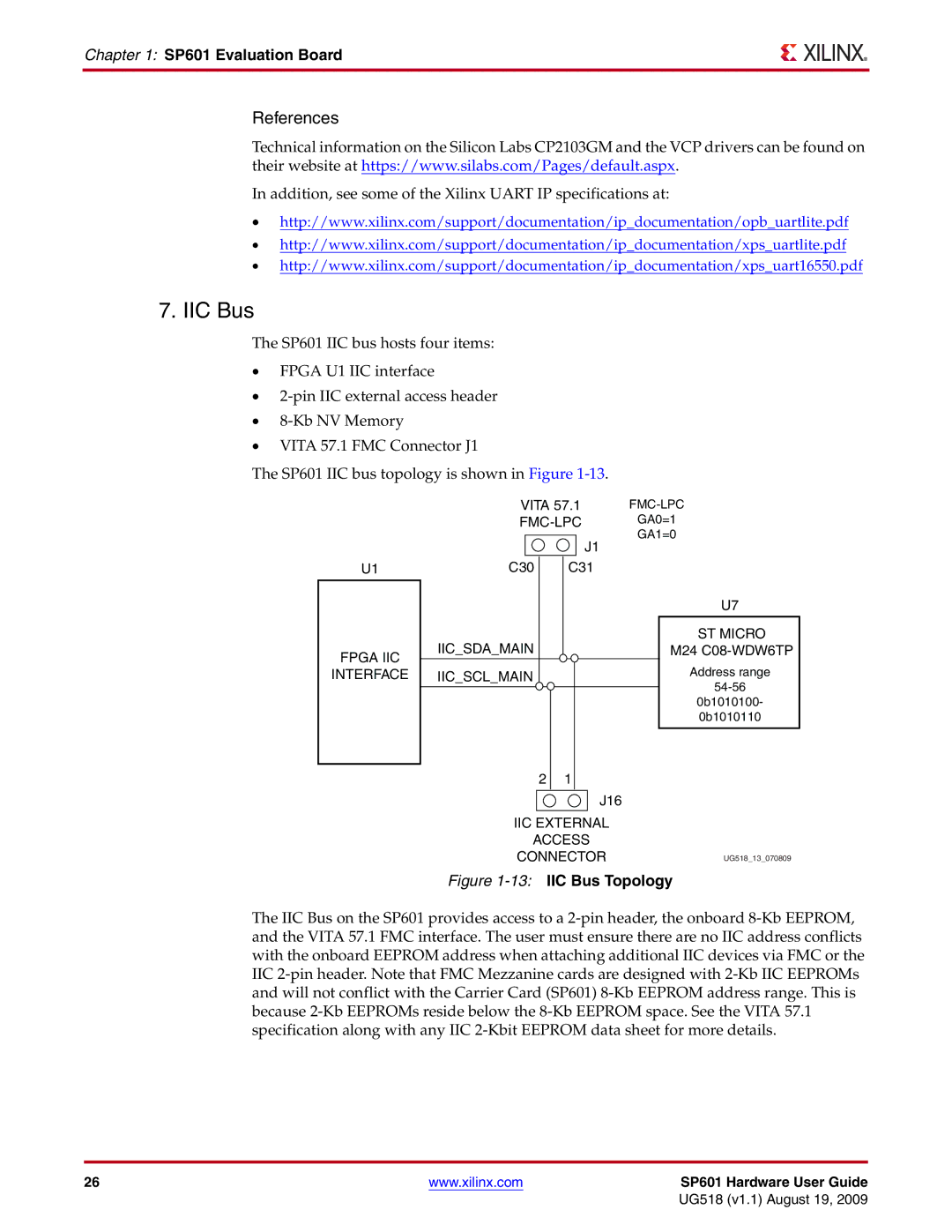
The SP601 IIC bus hosts four items:
•FPGA U1 IIC interface
•
•
•VITA 57.1 FMC Connector J1
The SP601 IIC bus topology is shown in Figure
U1
VITA 57.1 | ||
GA0=1 | ||
| J1 | GA1=0 |
|
| |
C30 | C31 |
|
U7
FPGA IIC
INTERFACE
IIC_SDA_MAIN
IIC_SCL_MAIN
2 1
J16
IIC EXTERNAL
ACCESS
CONNECTOR
ST MICRO
M24
Address range
0b1010100-
0b1010110
UG518_13_070809
Figure 1-13: IIC Bus Topology
The IIC Bus on the SP601 provides access to a
26 | www.xilinx.com | SP601 Hardware User Guide |
|
| UG518 (v1.1) August 19, 2009 |