Manuals
/
Yamaha
/
Home Audio
/
Stereo Amplifier
Yamaha
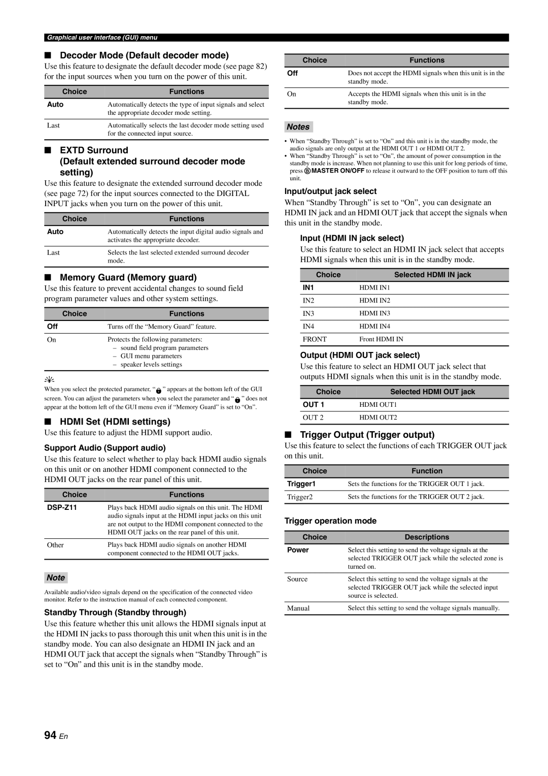
DSP-Z11 94 En, Decoder Mode Default decoder mode, EXTD Surround, Memory Guard Memory guard
Models:
DSP-Z11
1
94
150
150
Download
150 pages
25.38 Kb
91
92
93
94
95
96
97
98
Troubleshooting
Specs
Block diagrams
Audio and video signal flow
Connecting speakers
Advanced sound configurations
Supplied accessories
Set up your speakers
Basic procedure
Adjusting the tonal quality
Page 94
Image 94
Page 93
Page 95
Page 94
Image 94
Page 93
Page 95
Contents
OWNER’S MANUAL
AV Amplifier
English
Front panel
2 En
Remote control
3 En
4 En
Conditions
For U.K. customers
Caution: Read this before operating your unit
Special Instructions for U.K. Model
Introduction
Contents
6 En
Preparation
Introduction
7 En
Additional Information
Basic Operation
Notices
8 En
Introduction
Features
Introduction
Getting started
Features
10 En
Getting started
Supplied accessories
Installing batteries in the remote control
11 En
Opening and closing the front panel door
Using the remote control
VOLTAGE SELECTOR Asia and General models only
12 En
Quick start guide
Step 1: Set up your speakers
Step 3: Turn on the power and start playback
Enjoy Blu-rayDisc/HD DVD playback
Step 1: Set up your speakers
14 En
For other speaker configurations
Introduction
15 En
Quick start guide
General connection information
16 En
For further connections
Are you enjoying playback?
After using this unit
17 En
Step 3: Turn on the power and start playback
Additional features
Using various input sources
Using various sound features
Manually adjusting various parameters of
Preparation
Preparation
Connections
20 En
Connections
Rear panel
28 –
Placing speakers
21 En
7.2/7.1 or 6.2/6.1 -channelspeaker layout
22 En
5.2/5.1 -channelspeaker layout
Notes
Connecting speakers
23 En
Preparation
FRONT B speakers
For the 5.2/5.1 -channelspeaker setting
24 En
FRONT B speakers
Configuration 2: Front and rear
Using subwoofers
Configuration Front left and right
Configuration A single subwoofer
Using presence speakers
26 En
27 En
Connecting the speaker cable
Using bi-amplificationconnections
Preparation
28 En
Information on HDMI
Information on jacks and cable plugs
Audio jacks
Video signal flow
Audio and video signal flow
Audio signal flow
29 En
30 En
Connecting a TV monitor or projector
Notes
31 En
Connecting other components
Connecting a Blu-rayDisc or HD DVD player
Notes
32 En
Connecting a DVD player
Connecting set-topboxes
Connections
33 En
Connecting a DVD recorder
Connecting a VCR
Preparation
34 En
Connecting audio components
Notes
35 En
Connecting external amplifiers
Connecting a multi-formatplayer or an external
decoder
Using the TRIGGER OUT jacks
Connecting a Yamaha iPod universal dock
Using REMOTE IN/OUT jacks
36 En
Notes
Connecting the network
37 En
Preparation
Connecting the AC power cable
Connecting the power cable
Using the VIDEO AUX jacks on the front panel
AC OUTLETS SWITCHED
39 En
Setting the speaker impedance and language
Turning this unit on and off
A D V A N C E D S E T U P
t HD
Front panel display
40 En
qTRUE HD
RPR SBL SB SBR
41 En
Preparation
42 En
Before starting the automatic setup
Notes
A U T O S E T U P E N T E R T O S T A R T
Using the quick automatic setup
43 En
G U D S P - Z 1
44 En
Using the basic automatic setup
Notes
45 En
Reviewing the result of the automatic setup
Notes
46 En
Using advanced automatic setup
Notes
47 En
Preparation
5 412 3
48 En
3 12 4
9ENTER
Basic Operation
Using audio features
Basic Operation
Playback
Selecting the MULTI CH INPUT component
Basic procedure
Playback
50 En
Selecting the HDMI OUT jack
Using your headphones
Using the Zone B feature
Selecting the front speaker set
Selecting audio input jacks AUDIO SELECT
Using the sleep timer
Canceling the sleep timer
Muting the audio output
Basic controls in the GUI menu
53 En
Items in GUI menu
Basic Operation
Sound field program descriptions
Sound field programs
Selecting sound field programs
54 En
For audio music sources
55 En
Basic Operation
56 En
For visual sources of music
57 En
For various sources
Basic Operation
For game programs
58 En
For parties
For movie sources
Surround decoder mode
59 En
Stereo playback
THX Surround mode
programs with headphones SILENT CINEMA
Using CINEMA DSP HD³ mode
Using sound field programs without surround
Enjoying unprocessed input sources
Adjusting the speaker level
Using audio features
Adjusting the tonal quality
Enjoying pure hi-fisound
62 En
Recording
Notes
Internal Source Operation
Using iPod
Using Network/USB features
Internal Source Operation
Controlling iPod
Using iPod
Remote control operation
64 En
Notes
65 En
The functions of the play information display
Notes
66 En
Using Network/USB features
Navigating the network and USB menus
Notes
Remote control operation
67 En
Operation
68 En
Using a PC server or Yamaha MCX-2000
Installing Windows Media Player 11 on your PC
Registering this unit on the Yamaha MCX-2000
Storing your favorite Internet Radio stations
Using the Internet Radio
69 En
with bookmarks
70 En
Using shortcut buttons
Select an item by using numeric buttons 1-8B
P C / M C
Remote control features
Advanced sound configurations
Controlling this unit by using the Web browser
Using multi-zoneconfiguration
72 En
Advanced sound configurations
Selecting decoders
Selecting decoders for 2-channelsources
For 2-channelsources
Playing back sources with the THX Surround modes
73 En
For multi-channelsources
DSP-Z11 GUI menu tree
Graphical user interface GUI menu
74 En
Advanced
75 En
Operation
Graphical user interface GUI menu
Signal Info. Signal information
Manual Setup Manual setup menu
Auto Setup Automatic setup menu
GUI menu overview
77 En
Basic configuration of sound field programs
Stereo/Surround Stereo/Surround menu
Operation
78 En
Sound field parameter descriptions
Sur. Liveness
79 En
Liveness
SB. Liveness
Stereo program parameter descriptions
80 En
Decoder parameter descriptions
Initialize Program parameters initialization
Input Select
81 En
I/O Assignment Input/output assignment
Audio Select Audio input jack select
Volume Trim Volume trimming
82 En
Decoder Mode Decoder mode
83 En
Manual Setup Basic
THX Set THX settings
Multi CH Assign Multi channel assignment
Speaker Set Speaker settings
84 En
Notes
85 En
Speaker Distance Speaker distance
Notes
86 En
Manual Setup Volume
Manual Setup Sound
Speaker Level Speaker level
S-WaveControl Standing wave control
87 En
Dynamic Range Dynamic range
Parametric EQ Parametric equalizer
Tone Control Tone control
88 En
Lipsync Audio and video synchronization
Pure Direct Pure Direct
Manual Setup Video
89 En
Channel Mute Channel mute
HDMI Processing HDMI video processing
HDMI Resolution HDMI video signal resolution
90 En
Component I/P Component interlace
Party Mode Set Party mode settings
Manual Setup Multi Zone
Speaker B Speaker B setting
91 En
92 En
Manual Setup Network
Configuration Network configuration
Zone OSD Zone on-screendisplay
iPod iPod settings
Manual Setup Option
Front Panel Disp Front panel display setting
Audio Select Default audio input jack select
HDMI Set HDMI settings
Decoder Mode Default decoder mode
Default extended surround decoder mode setting
94 En
95 En
Signal Info Input signal information
Language
Audio Info. Audio information
Saving by the 7SYSTEM MEMORY buttons
Saving the current system settings
96 En
Saving by the GUI menu operation
Notes
Renaming the stored settings
97 En
Operation
Saved parameters for the main zone
Loading the stored system settings
98 En
Saved parameters for Zone 2, Zone 3, or Zone
according to the using situations
Using examples
Example 1: Switching the settings of this unit
99 En
100 En
room
Operation
101 En
USB features
Advanced
102 En
Remote control features
Controlling this unit, a TV, or other components
Controlling this unit
Selecting a component to be controlled
103 En
Controlling other components
Controlling optional components Option mode
LIGHT
Customizing the remote control
Setting remote control codes P-SET
104 En
105 En
P-SET DVD
04306
Notes
RNAME BD/HD
START DVD
BD/HD
Changing source names in the display window RNAME
MACRO
Macro programming features
HDDVD
107 En
108 En
Default macro functions
MACRO M:DVD
Programming macro operations MACRO
ERASE DVD
Clearing configurations
CLEAR L DVD
ERASE OK
remote control
Simplified remote control
Setting the controlling zone of the simplified
Replacing the battery in the simplified remote
Step 1: Planning the multi-zonesystem
Using multi-zoneconfiguration
Step1: Planning the multi-zonesystem
Step 3 Set the zone parameters
Using the internal amplifier of this unit
112 En
113 En
Using external amplifiers
Using the ZONE DIGITAL OUT COAXIAL jack
Notes
Connecting Zone video monitor
114 En
TRIGGER OUT jacks
115 En
REMOTE IN/OUT jacks
Operation
116 En
Step3: Setting the zone parameter
Controlling Zone 2, Zone 3, or Zone
M 2 3 F.PRNS EXTRA FRONT CENTER
ZONE
Setting the sleep timer for Zone 2, Zone 3, or
117 En
Zone
118 En
Using the party mode
Using the Zone OSD
Notes
Wake on RS-232Caccess RS-232CSTANDBY
Advanced setup
Using the advanced setup menu
119 En
Cooling fan operation mode FAN MODE
Recovery and backup of the system settings
120 En
Bi-amplifiermode BI-AMP
Specifications
Troubleshooting
Block diagrams
List of remote control codes
122 En
Troubleshooting
General
Information
123 En
Additional
HDMI
Remote control
124 En
Network and USB
Information
125 En
Additional
126 En
Auto Setup
iPod
Notes
Resetting the system
127 En
Information
Glossary
Component video signal
Composite video signal
128 En
129 En
DTS-HDHigh Resolution Audio
S-videosignal
LFE 0.1 channel
THX Ultra2
THX information
130 En
THX Cinema processing
Re-Equalization
Sound field program information
131 En
Adaptive Decorrelation
132 En
Sound output in each sound field program
Information
133 En
Additional
134 En
Available parameters for each sound field program
Frequency
Parametric equalizer information
135 En
Gain
136 En
Block diagrams
Audio section
Block diagrams
137 En
Video section
Information
Specifications
138 En
Notes
HDMI signal compatibility
139 En
Information
Index
140 En
Information
141 En
Additional
142 En
Information
143 En
Additional
List of remote control codes
144 En
Information
145 En
List of remote control codes
Additional
CABLE
146 En
List of remote control codes
SATELLITE TUNER
CD RECORDER
147 En
List of remote control codes
DVD PLAYER
Page
Page
2007
WK97760
All rights reserved
Top
Page
Image
Contents