Chapter 2: Installation | 8 |
|
|
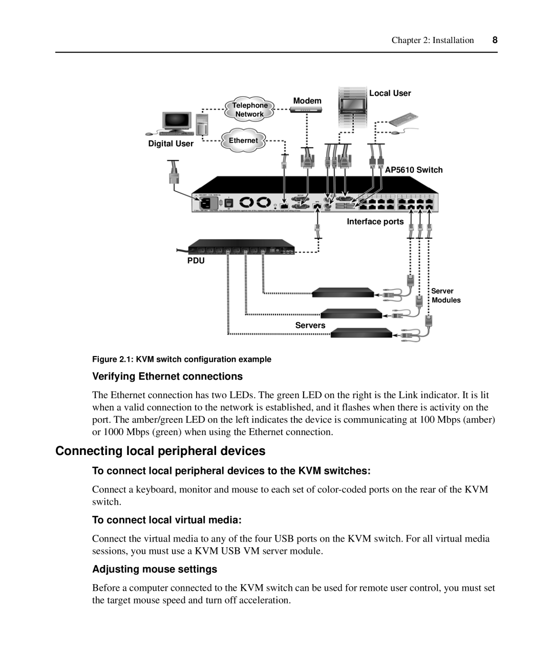
Local User
Telephone Modem
Network
Digital User | Ethernet |
AP5610 Switch
Interface ports
PDU
Server
Modules
Servers
Figure 2.1: KVM switch configuration example
Verifying Ethernet connections
The Ethernet connection has two LEDs. The green LED on the right is the Link indicator. It is lit when a valid connection to the network is established, and it flashes when there is activity on the port. The amber/green LED on the left indicates the device is communicating at 100 Mbps (amber) or 1000 Mbps (green) when using the Ethernet connection.
Connecting local peripheral devices
To connect local peripheral devices to the KVM switches:
Connect a keyboard, monitor and mouse to each set of
To connect local virtual media:
Connect the virtual media to any of the four USB ports on the KVM switch. For all virtual media sessions, you must use a KVM USB VM server module.
Adjusting mouse settings
Before a computer connected to the KVM switch can be used for remote user control, you must set the target mouse speed and turn off acceleration.