SERVSWITCH™ MULTI
10.4.1DISPLAY CHASSIS CONFIGURATION
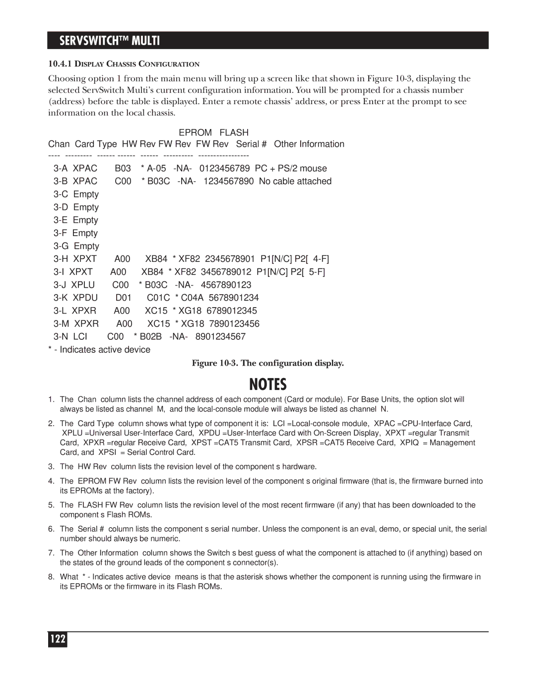
Choosing option 1 from the main menu will bring up a screen like that shown in Figure
EPROM | FLASH |
Chan Card Type HW Rev FW Rev | FW Rev Serial # Other Information |
----
XPAC | B03 | * | 0123456789 | PC + PS/2 mouse | |||
XPAC | C00 | * B03C | 1234567890 | No cable attached | |||
Empty |
|
|
|
|
|
| |
Empty |
|
|
|
|
|
| |
Empty |
|
|
|
|
|
| |
Empty |
|
|
|
|
|
| |
Empty |
|
|
|
|
|
| |
XPXT | A00 | XB84 | * XF82 | 2345678901 | P1[N/C] P2[ | ||
XPXT | A00 | XB84 | * XF82 | 3456789012 | P1[N/C] P2[ | ||
XPLU | C00 | * B03C | 4567890123 |
|
| ||
XPDU | D01 | C01C | * C04A | 5678901234 |
|
| |
XPXR | A00 | XC15 | * XG18 | 6789012345 |
|
| |
XPXR | A00 | XC15 | * XG18 | 7890123456 |
|
| |
LCI | C00 | * B02B | 8901234567 |
|
| ||
* - Indicates active device
Figure 10-3. The configuration display.
NOTES
1.The “Chan” column lists the channel address of each component (Card or module). For Base Units, the option slot will always be listed as channel “M,” and the
2.The “Card Type” column shows what type of component it is:
3.The “HW Rev” column lists the revision level of the component’s hardware.
4.The “EPROM FW Rev” column lists the revision level of the component’s original firmware (that is, the firmware burned into its EPROMs at the factory).
5.The “FLASH FW Rev” column lists the revision level of the most recent firmware (if any) that has been downloaded to the component’s Flash ROMs.
6.The “Serial #” column lists the component’s serial number. Unless the component is an eval, demo, or special unit, the serial number should always be numeric.
7.The “Other Information” column shows the Switch’s best guess of what the component is attached to (if anything) based on the states of the ground leads of the component’s connector(s).
8.What “* - Indicates active device” means is that the asterisk shows whether the component is running using the firmware in its EPROMs or the firmware in its Flash ROMs.