SERVSWITCH™ MULTI
6.4 Installing Your Expansion Cards
To install a Transmit or Receive Expansion Card in a ServSwitch Multi Base Unit or Expansion Chassis, take these steps:
1.Position the ServSwitch Multi so that its rear panel is facing you, as shown in Figure
2.Choose an available slot. In most cases, any slot that is covered with a blank (connectorless) panel will be available. However, note that on the Base Unit and MX (if you must use any of these), the
3.Remove the blank panel covering the available slot by unscrewing the two
4.Find the two
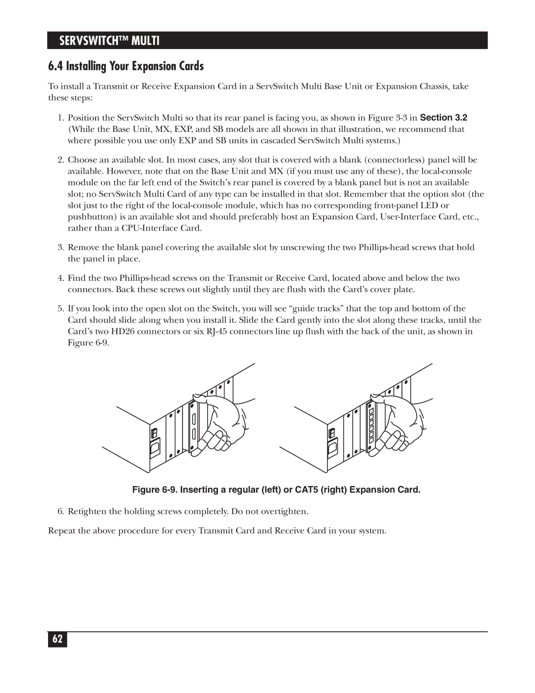
5.If you look into the open slot on the Switch, you will see “guide tracks” that the top and bottom of the Card should slide along when you install it. Slide the Card gently into the slot along these tracks, until the Card’s two HD26 connectors or six
Figure 6-9. Inserting a regular (left) or CAT5 (right) Expansion Card.
6. Retighten the holding screws completely. Do not overtighten.
Repeat the above procedure for every Transmit Card and Receive Card in your system.
62