CHAPTER 4: Installing
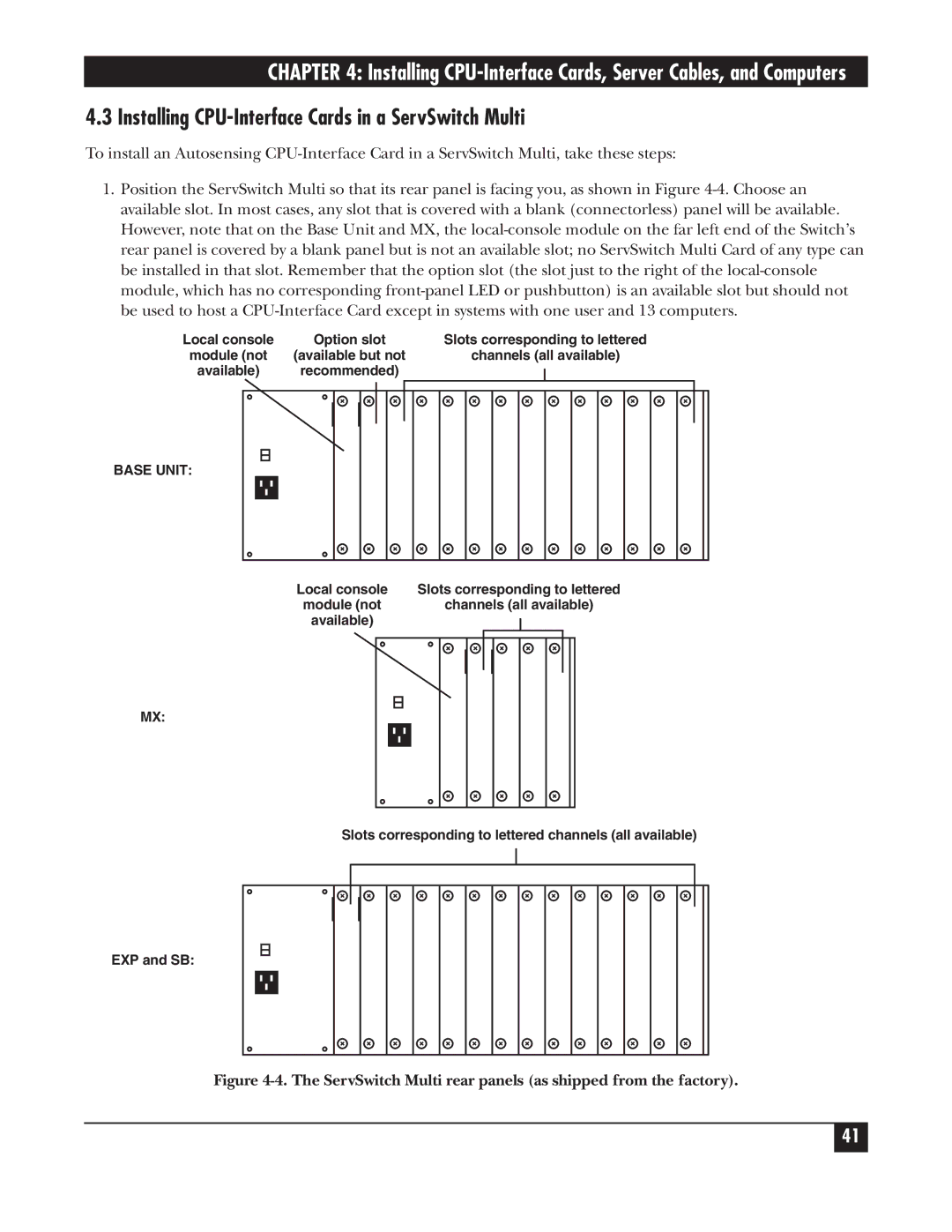
4.3 Installing CPU-Interface Cards in a ServSwitch Multi
To install an Autosensing
1.Position the ServSwitch Multi so that its rear panel is facing you, as shown in Figure
Local console | Option slot | Slots corresponding to lettered | |||||
module (not | (available but not | channels (all available) | |||||
available) | recommended) |
|
| ||||
|
| ||||||
|
|
|
|
|
|
|
|
|
|
|
|
|
|
|
|
BASE UNIT:
Local console | Slots corresponding to lettered | |||
module (not | channels (all available) | |||
available) |
|
|
|
|
|
|
|
| |
|
|
|
|
|
|
|
|
|
|
MX:
Slots corresponding to lettered channels (all available)
EXP and SB:
Figure 4-4. The ServSwitch Multi rear panels (as shipped from the factory).
41