SERVSWITCH™ MULTI
6.3 Configuring Your Expansion Cards
You will need to configure your Transmit and Receive Cards before you install them in your ServSwitch Multi system. There are two steps to this process:
1.Setting the DIP switch on each Transmit Card for the proper ServSwitch Multi unit address.
2.Setting the jumpers on each Transmit and Receive Card for the length of Expansion Cable that will be attached to each of the Card’s two ports.
6.3.1SETTING THE TRANSMIT CARD’S
All ServSwitch Multis that contain Transmit Cards must be given a unique unit address that you determine. Unit addresses are numeric, and may be any value from 1 to 254 (addresses “0” and “255” are reserved). Make sure to set every Transmit Card that you’ll be installing in a given ServSwitch Multi to the same unit address; if a Switch detects that it contains Transmit Cards with different addresses, it will not operate at all. Make very sure not to set Transmit Cards installed in different Switch units to the same address; otherwise your system will operate, but it will malfunction, and finding and fixing the problem could be tough.
To set the
1.Gather together all of the Transmit Cards that you will be installing in a particular ServSwitch Multi.
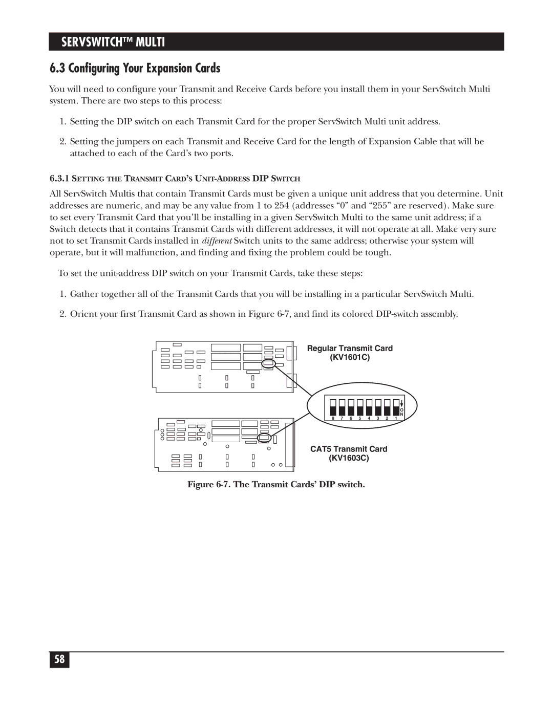
2.Orient your first Transmit Card as shown in Figure
Regular Transmit Card
(KV1601C)
O
N
8 7 6 5 4 3 2 1
CAT5 Transmit Card
(KV1603C)
Figure 6-7. The Transmit Cards’ DIP switch.
58