SERVSWITCH™ MULTI
6.1 Placing the ServSwitch Multi
NOTE
Here and elsewhere in this chapter you will see diagrams in which ServSwitch Multis units are identified as “Switch 0.” You will notice that all such Switches have Receive Cards installed in them, but no Transmit Cards. Do not set the address of any unit with a Transmit Card installed in it to zero; your system will not work. The address zero is reserved as the operating address for all ServSwitch Multis in which no Transmit Cards are
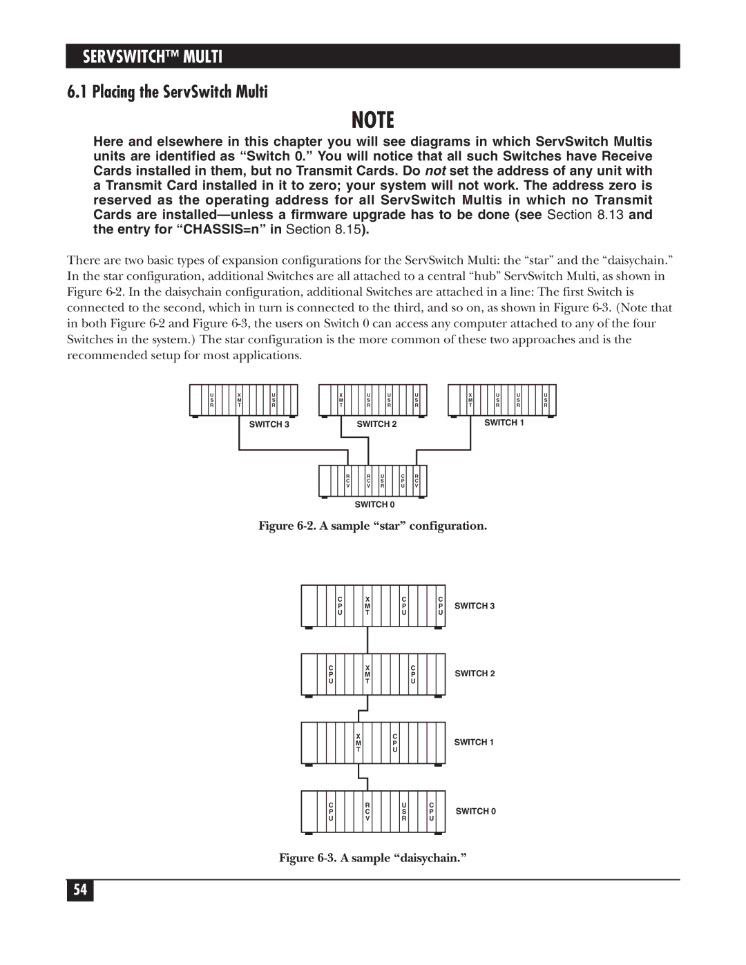
There are two basic types of expansion configurations for the ServSwitch Multi: the “star” and the “daisychain.” In the star configuration, additional Switches are all attached to a central “hub” ServSwitch Multi, as shown in Figure
|
|
|
| U |
|
|
| X |
|
|
|
| U |
|
|
|
|
|
|
|
| S |
|
|
| M |
|
|
|
| S |
|
|
|
|
|
|
|
| R |
|
|
| T |
|
|
|
| R |
|
|
|
|
|
|
|
|
|
|
|
|
|
|
|
|
|
|
|
|
|
|
SWITCH 3
|
|
|
| X |
|
|
| U |
|
| U |
|
|
| U |
|
| |||||
|
|
|
| M |
|
|
| S |
|
| S |
|
|
| S |
|
| |||||
|
|
|
| T |
|
|
| R |
|
| R |
|
|
| R |
|
| |||||
|
|
|
|
|
|
|
|
|
|
|
|
|
|
|
|
|
|
|
|
|
|
|
|
|
|
|
|
|
|
| SWITCH 2 |
|
|
|
|
|
|
| |||||||
|
|
|
|
|
|
|
|
|
|
|
|
|
|
|
|
|
|
|
|
|
|
|
|
|
|
|
|
|
|
|
|
|
|
|
|
|
|
|
|
|
|
|
|
|
|
|
|
|
|
|
|
|
|
|
|
|
|
|
|
|
|
|
|
|
|
|
|
|
|
|
|
|
|
| R |
|
| R |
| U |
|
| C |
| R |
| |||||
|
|
|
|
|
| C |
|
| C |
| S |
|
| P |
| C |
| |||||
|
|
|
|
|
| V |
|
| V |
| R |
|
| U |
| V |
| |||||
|
|
|
|
|
|
|
|
|
|
|
|
|
|
|
|
|
|
|
|
|
|
|
|
|
|
| X |
|
|
| U |
|
| U |
|
|
| U |
|
| |
|
|
|
| M |
|
|
| S |
|
| S |
|
|
| S |
|
| |
|
|
|
| T |
|
|
| R |
|
| R |
|
|
| R |
|
| |
|
|
|
|
|
|
|
|
|
|
|
|
|
|
|
|
|
|
|
SWITCH 1
SWITCH 0
Figure 6-2. A sample “star” configuration.
C P U
X
M
T
C P U
C P U
SWITCH 3
C P U
X
M
T
C P U
SWITCH 2
X
M
T
C P U
SWITCH 1
C P U
R C V
U S R
C P U
SWITCH 0
Figure 6-3. A sample “daisychain.”
54