CHAPTER 5: Installing Management and Serial Control Cards and Associated Equipment
5.2 The Cards and Cables Illustrated
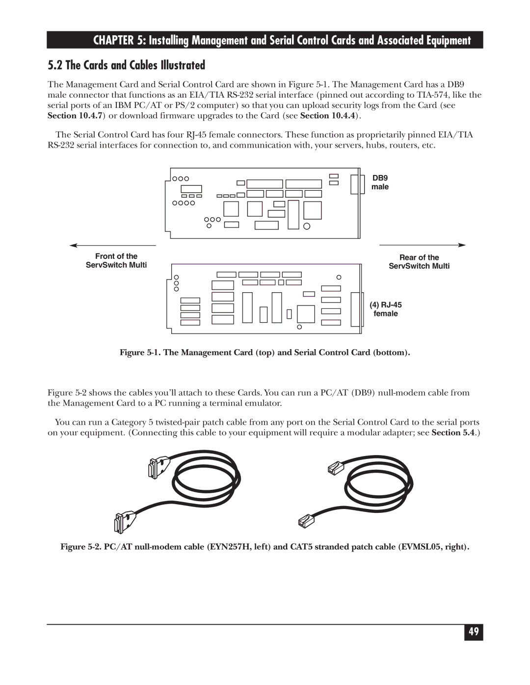
The Management Card and Serial Control Card are shown in Figure
The Serial Control Card has four
DB9
male
Front of the |
|
| Rear of the | |||||||
ServSwitch Multi |
|
| ServSwitch Multi | |||||||
|
|
|
|
|
|
|
|
|
|
|
|
|
|
|
|
|
|
|
|
|
|
|
|
|
|
|
|
|
|
|
|
|
|
|
|
|
|
|
|
|
|
|
|
|
|
|
|
|
|
|
|
|
|
|
|
|
|
|
|
|
|
|
|
|
|
|
|
|
|
|
|
|
|
|
|
|
(4)
female
Figure 5-1. The Management Card (top) and Serial Control Card (bottom).
Figure 5-2 shows the cables you’ll attach to these Cards. You can run a PC/AT (DB9) null-modem cable from the Management Card to a PC running a terminal emulator.
You can run a Category 5 twisted-pair patch cable from any port on the Serial Control Card to the serial ports on your equipment. (Connecting this cable to your equipment will require a modular adapter; see Section 5.4.)
Figure 5-2. PC/AT null-modem cable (EYN257H, left) and CAT5 stranded patch cable (EVMSL05, right).
49