2.048Mbps Wireless Modem
Appendix A - V.35/RS-530/X.21 Applications
DCE/DTE Configuration
The following is a description of the possible configurations when connecting V.35/RS- 530/X.21 end equipment to the 2.048Mbps Wireless Modem. The configurations described are applicable to software version 1.5 and up with a
V.35/RS-530/X.21 Standards
These standards define the operation of a communications channel, consisting of end equipment units connected to the communications channel by a modem. The standards define DATA circuits and LOCK circuits to time them.
The end equipment is normally called DTE and the modem is normally called DCE. A DTE connects to a DCE. DTE or DCE assignments define the direction of the DATA, CLOCK, and CONTROL circuits supported by the standard.
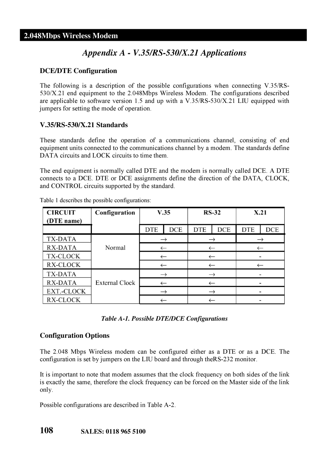
Table 1 describes the possible configurations:
Table A-1. Possible DTE/DCE Configurations
Configuration Options
The 2.048 Mbps Wireless modem can be configured either as a DTE or as a DCE. The configuration is set by jumpers on the LIU board and through
It is important to note that modem assumes that the clock frequency on both sides of the link is exactly the same, therefore the clock frequency can be forced on the Master side of the link only.
Possible configurations are described in Table