2.048Mbps Wireless Modem
For further information on antennas, cables and related accessories see Chapter 2, Installation, antennas and Accessories.
Antenna Interface
Antenna interface to the 2.048Mbps Wireless Modem is via two SMA connectors on the rear panel; Transmit antenna should be connected to TX and Receive antenna to RX.
Front Panel Indicators
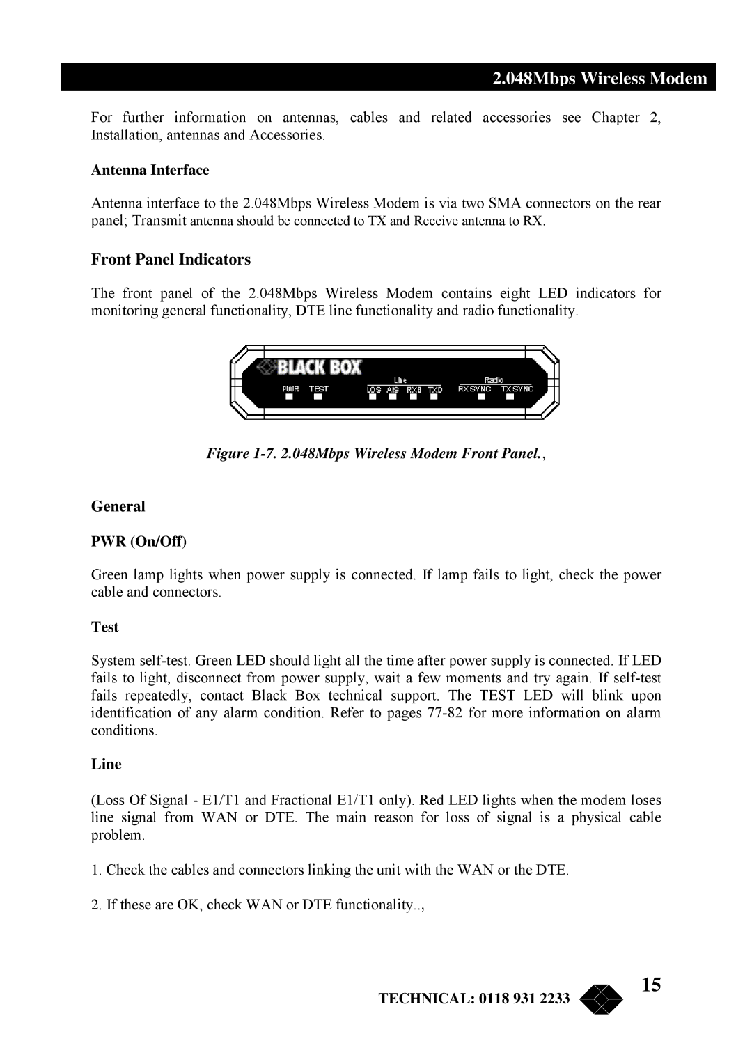
The front panel of the 2.048Mbps Wireless Modem contains eight LED indicators for monitoring general functionality, DTE line functionality and radio functionality.
Figure 1-7. 2.048Mbps Wireless Modem Front Panel.,
General
PWR (On/Off)
Green lamp lights when power supply is connected. If lamp fails to light, check the power cable and connectors.
Test
System
Line
(Loss Of Signal - E1/T1 and Fractional E1/T1 only). Red LED lights when the modem loses line signal from WAN or DTE. The main reason for loss of signal is a physical cable problem.
1.Check the cables and connectors linking the unit with the WAN or the DTE.
2.If these are OK, check WAN or DTE functionality..,
TECHNICAL: 0118 931 2233
15