2.048Mbps Wireless Modem
2.Loosen the screws on the
3.Tighten the screws on the
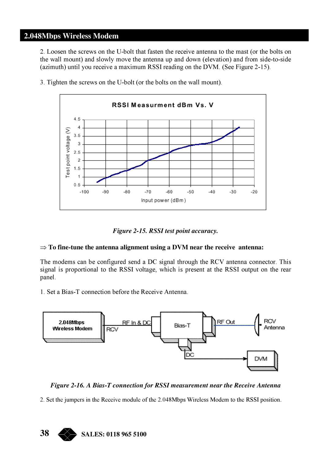
Figure 2-15. RSSI test point accuracy.
⇒To
The modems can be configured send a DC signal through the RCV antenna connector. This signal is proportional to the RSSI voltage, which is present at the RSSI output on the rear panel.
1. Set a
Figure 2-16. A Bias-T connection for RSSI measurement near the Receive Antenna
2. Set the jumpers in the Receive module of the 2.048Mbps Wireless Modem to the RSSI position.
38 | SALES: 0118 965 5100 |
