30
2.048Mb
p
s Wireless Modem
SALES: 0118 965 5100
NF2 = Noise Figure of the cable = Loss of cable
NF3 = Noise Figure of the modem = 2.8
G1 = Gain of LNA 10 = 10
G2 = Gain of the cable = 1/Loss of cable
(*) All values above are taken in absolute value (not dB).
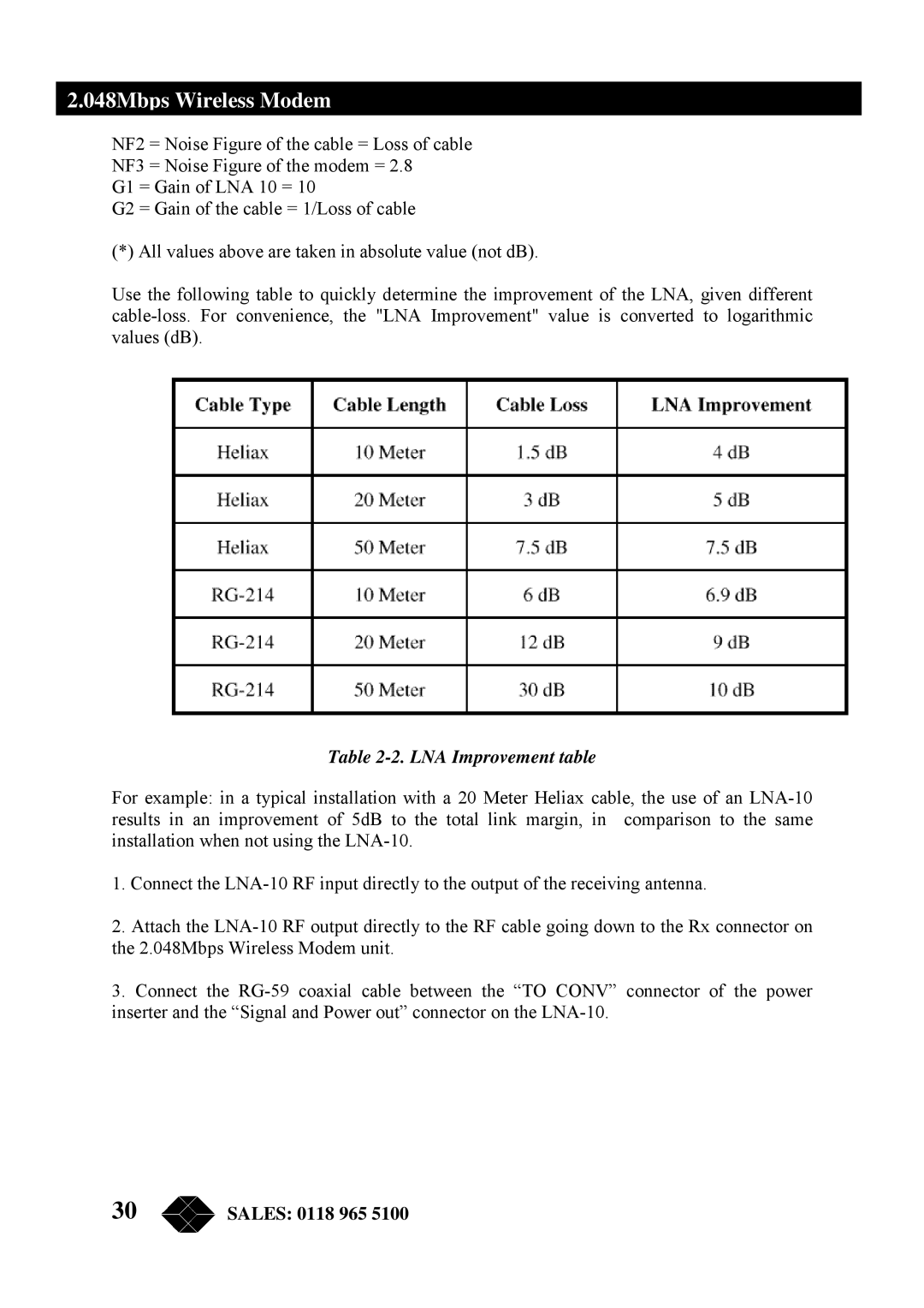
Use the following table to quickly determine the improvement of the LNA, given different
cable-loss. For convenience, the "LNA Improvement" value is converted to logarithmic
values (dB).
Table 2-2. LNA Improvement table
For example: in a typical installation with a 20 Meter Heliax cable, the use of an LNA-10
results in an improvement of 5dB to the total link margin, in comparison to the same
installation when not using the LNA-10.
1. Connect the LNA-10 RF input directly to the output of the receiving antenna.
2. Attach the LNA-10 RF output directly to the RF cable going down to the Rx connector on
the 2.048Mbps Wireless Modem unit.
3. Connect the RG-59 coaxial cable between the “TO CONV” connector of the power
inserter and the “Signal and Power out” connector on the LNA-10.